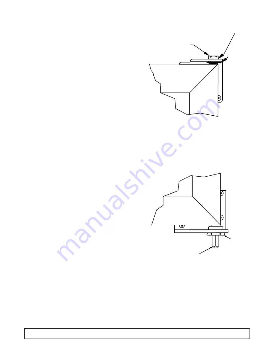
TORSION ROD HINGED DOORS - Maintenance & Removal
GLASS DOOR CABINETS ONLY
MAINTENANCE – ALIGNING DOORS
Proper alignment of the cabinet doors will eliminate
hinge binding and provide correct gasket seal.
1. Check the level of the cabinet and door alignment
by firmly closing each door. Observe the movement
of the other doors. They should open slightly, then
close and seal.
2. The hinge wings fastened to the cabinet door have
slotted mounting holes for adjustment.
3. Additional adjustment can be made by adding
shims between the hinge wing and either the door
or the cabinet face.
REMOVING DOORS:
1. Loosen lower hex nut (Nut “A”) and release tension
on the torsion rod.
2. Remove the hitch pin from the upper hinge pin.
3. Hold the door steady and unscrew the pin at top of
the door. The door can now be lifted out of the lower
hinge- bracket
REINSTALLING DOORS:
1. Set lower square shaft on door in lower hinge
bracket
2. Insert top hinge pin and tighten to 12 ft./lbs. torque.
NOTE: Washer must be in place so top pin will not
loosen and disconnect from door hinge.
3. Insert hitch pin through hole in upper hinge pin.
4. Run Nut “A” up snug. (You may have to loosen Nut
“A” as you tighten tension as noted in Step 5.)
5. Set tension on door by turning square shaft in the
direction the door closes. Set tension so that the
door will self close when opened approximately 1".
(Do not overtighten so door will slam.) Tighten Nut
“A” so tension can be maintained.
NUT "A"
SQUARE
SHAFT
HINGE PIN
WASHER
HITCH
PIN
TORQUE ROD REMOVAL
1. Loosen nut “A” to remove door.
2. Attach vice grips to shaft.
3. Drive torque rod out of door.
4. Install new rod into keyway slot in door frame.
5. Reattach nut after installing door.
6. Turn shaft clockwise then lock nut “A”.
7. Add torque until door will close by itself.
50
MAINTENANCE & REPAIR
Summary of Contents for BT30RF- EXPR
Page 15: ...SECTION II...
Page 26: ...ELECTRICAL BOX WIRING DIAGRAM 00 0056 00 WIRING DIAGRAM 25...
Page 27: ...ELECTRICAL BOX WIRING DIAGRAM 00 0057 00 26 WIRING DIAGRAM...
Page 28: ...ELECTRICAL BOX WIRING DIAGRAM 00 0064 00 WIRING DIAGRAM 27...
Page 49: ...INSTRUCTIONS SOLID DOOR REMOVAL INSTALLATION ADJUSTMENT 48 MAINTENANCE REPAIR...
Page 63: ...CASTER INSTALLATION INSTRUCTIONS 62 MAINTENANCE REPAIR...
Page 69: ...ELECTRICAL REFRIGERATION INFORMATION BT30RF EXPR Explosion Proof Refrigerator Freezer...
Page 79: ...ELECTRICAL REFRIGERATION INFORMATION ST260RI ST260RIR...
Page 81: ...MODULE 1 ANALOGIC PARAMETERS MODULE 1 PARAMETERS 83...
Page 83: ...MODULE 1 DAYTRONICS PARAMETERS MODULE 1 PARAMETERS 85...
Page 102: ...EVAPORATOR FAN SHROUD ASSEMBLY 104 EVAPORATOR FAN SHROUD ILLUSTRATION...
Page 105: ...EVAPORATOR FAN AREA BT30RSFMS BT50RSFMS EVAPORATOR FAN AREA ILLUSTRATION 107...


