TEMPERATURE CONTROL
BT30RF-EXPR
Located on the unit compartment, behind the front
grill. The temperature setting may be changed by:
1. Remove the two screws that hold the cover in
place;
2 Adjust the temperature control knob to desired cav-
ity temperature. Replace cover.
The thermostat dial is calibrated in degrees
Fahrenheit, but does not indicate temperatures inside
the storage compartment. Typical performance for
thermostat control settings is listed below. Cabinet
thermostats are factory preset for 0°F.
Thermostat Setting
Freezer Temp.
Cavity Temp.
+20°
+11°F
51°
+10°
+12°F
41°
+5°
+10°F
41°
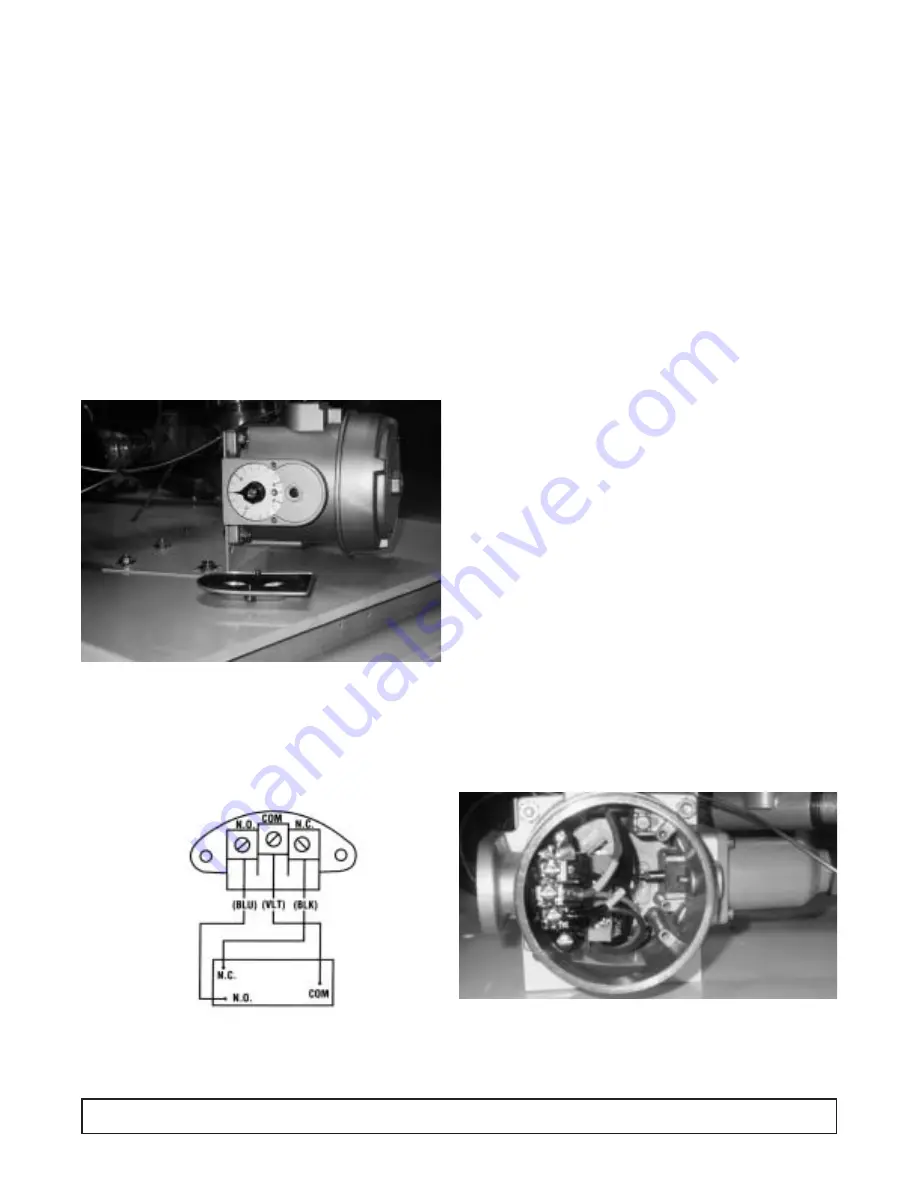
SWITCH HOUSING COVER REMOVED
IMPORTANT: Use only factory authorized replace-
ment parts and procedures.
CAUTION:
Always disconnect supply circuits
before removing explosion proof cover.
REPLACEMENT OF SWITCHES
Types E121 & F120
1. Remove cover, (2) switch mounting screws, switch
and insulator.
2. Disconnect (3) switch wires at switch terminal.
3. Install new switch and wire per SET POINT
ADJUSTMENTS.
4. Mount switch and insulator inside enclosure and
recalibrate per SET POINT ADJUSTMENTS.
SET POINT ADJUSTMENTS
NOTE: For set point adjustments and recalibration,
connect control to a calibrated temperature
source and stabilize unit.
TYPE E121
Adjust set point by turning external knob and pointer to
desired setting on scale.
Recalibration—adjusting set point after replacing
switch(es) and/or thermal assembly:
Slowly turn adjustment knob until switch transfers.
Compare switch transfer point to actual temperature. If
they do not agree, loosen set screws on adjustment
knob and align pointer to indicate actual temperature.
2
2
1
1
76
TEMPERATURE CONTROL
Summary of Contents for BT30RF- EXPR
Page 15: ...SECTION II...
Page 26: ...ELECTRICAL BOX WIRING DIAGRAM 00 0056 00 WIRING DIAGRAM 25...
Page 27: ...ELECTRICAL BOX WIRING DIAGRAM 00 0057 00 26 WIRING DIAGRAM...
Page 28: ...ELECTRICAL BOX WIRING DIAGRAM 00 0064 00 WIRING DIAGRAM 27...
Page 49: ...INSTRUCTIONS SOLID DOOR REMOVAL INSTALLATION ADJUSTMENT 48 MAINTENANCE REPAIR...
Page 63: ...CASTER INSTALLATION INSTRUCTIONS 62 MAINTENANCE REPAIR...
Page 69: ...ELECTRICAL REFRIGERATION INFORMATION BT30RF EXPR Explosion Proof Refrigerator Freezer...
Page 79: ...ELECTRICAL REFRIGERATION INFORMATION ST260RI ST260RIR...
Page 81: ...MODULE 1 ANALOGIC PARAMETERS MODULE 1 PARAMETERS 83...
Page 83: ...MODULE 1 DAYTRONICS PARAMETERS MODULE 1 PARAMETERS 85...
Page 102: ...EVAPORATOR FAN SHROUD ASSEMBLY 104 EVAPORATOR FAN SHROUD ILLUSTRATION...
Page 105: ...EVAPORATOR FAN AREA BT30RSFMS BT50RSFMS EVAPORATOR FAN AREA ILLUSTRATION 107...


