41
Models C708/C709/C716/C717
Controls, Systems and Operations
060207
Jumper Pins - UVC3
JUMPER
PINS
FUNCTION
Jumper installed -- normal applications using refrigerated mix.
JP1
Pins 1 & 2
No jumper installed -- general market configuration using
non--refrigerated mix. Ignores hopper temperature lockout parameters to
allow adding non--refrigerated mix into the hopper.
Pins 3 & 4
No jumper -- Not used
(for future development)
Pins 1 & 2
Domestic configuration -- jumper installed.
Hopper temperature not
displayed on screen. Heat symbol symbols are only active when a
lockout condition has occurred. Standby symbols are disabled.
JP2
Pins 1 & 2
International configuration -- no jumper.
Hopper temperature is
displayed on screen. Manual heat cycle starts by touching the HEAT
symbol. Standby symbols are functional.
Pins 3 & 4
No jumper -- Not used
(for future development)
JP3
Pins 1 & 2
Remove jumper to disable audible device located on UVC3 control.
JP3
Pins 3 & 4
No jumper -- Not used
(for future development)
Note:
The new UVC control board jumper blocks have 4 pins. Jumper on pins 1 & 2 are active. Pins 3 & 4 are
open for future development.
Programming Jumpers
Interface Board
W5
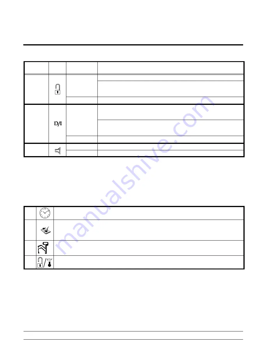
If a jumper is present on the left interface board, the real time clock can be changed in any
mode.
W4
Installing a jumper on the left or right interface board forces the liquid solenoid valves, the hot
gas soleniod valves, and the suction solenoid to be energized on the corresponding side of the
unit. Removing the jumper ends their operation. This is used for reclaiming and evacuation of
the refrigeration system only, or manual cycling of the solenoid valves for service check.
W3
A jumper on the W3 of the left interface board enables the syrup heaters.
W2
If a jumper is present on the left interface board, it resets the brush clean date. If a jumper is
present on the right interface board, it enables the 59
°
F (15
°
C) product temperature fault.
Summary of Contents for C708
Page 1: ...Models C708 C709 C716 C717 Heat Treatment Soft Serve Freezers Service Manual 059061 S 6 15 05 ...
Page 2: ......
Page 6: ...Table of Contents Models C708 C709 C716 C717 Notes ...
Page 22: ...16 Introduction Models C708 C709 C716 C717 Notes ...
Page 49: ...43 Models C708 C709 C716 C717 Systems Controls and Operations C708 C709 Control Overview ...
Page 50: ...44 Systems Controls and Operations Models C708 C709 C716 C717 C716 C717 Control Overview ...
Page 53: ...47 Models C708 C709 C716 C717 Systems Controls and Operations Refrigeration Schematic ...
Page 70: ...64 Troubleshooting Models C708 C709 C716 C717 Notes ...
Page 73: ...67 Models C708 C709 C716 C717 Parts Notes ...
Page 74: ...68 Parts Models C708 C709 C716 C717 Model C708 Exploded View ...
Page 78: ...72 Parts Models C708 C709 C716 C717 Model C709 Exploded View ...
Page 82: ...76 Parts Models C708 C709 C716 C717 Model C716 Exploded View ...
Page 86: ...80 Parts Models C708 C709 C716 C717 Model C717 Exploded View ...
Page 133: ...C708 C709 057010 27 Rev 6 05 ...
Page 134: ...C708 C709 057010 33 Rev 6 05 ...
Page 135: ...C708 C709 057010 40 Rev 6 05 ...
Page 136: ...C708 C709 057010 58 Rev 6 05 ...
Page 137: ...Model C716 059900 27 Rev 2 06 ...
Page 138: ...Model C716 059900 27 Inset 1 2 06 ...
Page 139: ...Model C716 059900 27 Inset 2 2 06 ...
Page 140: ...Model C716 059900 33 Rev 2 06 ...
Page 141: ...Model C716 059900 40 Rev 2 06 ...
Page 142: ...Model C716 059900 58 Rev 2 06 ...
Page 143: ...Model C717 059901 27 6 05 ...
Page 144: ...Model C717 059901 27 Inset 1 6 05 ...
Page 145: ...Model C717 059901 27 Inset 2 6 05 ...
Page 146: ...Model C717 059901 33 6 05 ...
Page 147: ...Model C717 059901 40 6 05 ...
Page 148: ...Model C717 059901 58 6 05 ...


