background image

8

To replace or inspect filters in accessory filter rack (See Fig. 2):

1. Remove the filter access panel using a 5/16--in. nut driver.
2. Remove the filter(s) by pulling it out of the unit. If the

filter(s) is dirty, clean or replace with a new one.

When installing the new filter(s), note the direction of the airflow
arrows on the filter frame, which should be pointing at the indoor

coil.

3. Reinstall filter access panel ensuring opening is air and

watertight.

If you have difficulty locating your air filter(s) or have questions

concerning proper filter maintenance, contact your dealer for
instructions. When replacing filters, always use the same size and

type of filter that was supplied originally by the installer. See Table
1 for filter sizes supplied with accessory filter rack.

Replacing or inspecting filters in units with

economizers

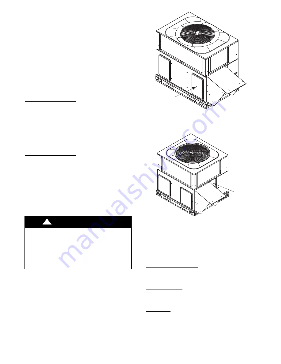
Small Chassis (See Fig. 8)

1. Remove return air duct cover at rear of unit using a 5/16--in.

nut driver.

2. Remove the filter(s) by pulling it out and through the unit

duct opening. If filter is dirty, replace both filters with new
ones.

When installing the new filters, note the direction of the airflow

arrows on the filter frame, which should be pointing at the indoor

coil.

3. Reinstall duct cover ensuring opening is air and watertight.

Large Chassis (See Fig. 9)

1. Remove filter access door using a 5/16--in. nut driver.
2. Remove the filter(s) by pulling it out and through the unit

filter access door. If filter is dirty, replace both filters with
new ones.

Units with bent indoor coils, install 24 x 18 x 1 (610 x 457 x 25

mm) filter first and then install 24 x 16 x 1 (610 x 406 x 25) filter.
When installing the new filters, note the direction of the airflow
arrows on the filter frame, which should be pointing at the indoor

coil.

3. Reinstall filter access door ensuring opening is air and

watertight.

UNIT OPERATION HAZARD

Failure to follow this caution may result in

property

damage.
Never operate your unit without filters in place. An

accumulation of dust and lint on internal parts of your unit

can cause loss of efficiency and blower motor and/or

compressor damage.

!

CAUTION

RETURN

DUCT COVER

(Remove for

filter access)

SMALL CHASSIS

A10063

Fig. 8 -- Small Chassis Filter Access

LARGE CHASSIS

FILTER

ACCESS

PANEL

A10062

Fig. 9 -- Large Chassis Filter Access

Fans and Fan Motors

Periodically check the condition of fan wheels and housings and

fan motor shaft bearings. Contact your dealer for the required
annual maintenance.

Indoor and Outdoor Coils

Cleaning of the coils should only be done by qualified service

personnel. Contact your dealer for the required annual
maintenance.

Condensate Drain

The drain pan and condensate drain line should be checked and

cleaned at the same time the cooling coils are checked by your
dealer.

Compressor

All compressors are factory shipped with a normal charge of the

correct type and quantity of refrigeration grade oil. A compressor
should rarely require additional oil.

Summary of Contents for Comfort 48VT-C

Page 1: ...__________________________________ _____________________________________________ _____________________________________________ INSTALLATION INFORMATION Date Installed________________________________ DEALERSHIP CONTACT INFORMATION Company Name_______________________________ Address______________________________________ _____________________________________________ Phone Number _____________________...

Page 2: ...ury death or property damage Installation and servicing of this equipment can be hazardous due to mechanical and electrical components Only trained and qualified personnel should install repair or service this equipment WARNING FIRE EXPLOSION ELECTRICAL SHOCK HAZARD Failure to follow this warning could result in personal injury death or property damage Do not use this unit if any part has been und...

Page 3: ...re to start unit The induced draft combustion air fan will start Main gas valve will open and main burners should ignite within 5 seconds If the burner does not light within 5 seconds the ignition module will go into a Retry Mode after a period of approximately 22 seconds following the 5 second ignition period If the burners do not light within 15 minutes of the initial call for heat there is a lo...

Page 4: ...FAN control and a SYSTEM or MODE control Refer to your thermostat owner s manual for more information To better protect your investment and to eliminate unnecessary service calls familiarize yourself with the following facts 1 During heat pump heating increasing the thermostat setting more than 2_F 1 1_C may cause the supplemental gas heat to be turned on for a short period of time to satisfy the ...

Page 5: ...5 55 STEP 1 STEP 2 CL O S E STEP 3 OFF ON MAIN STEP 4 STEP 7 OFF ON MAIN STEP 8 STEP 5 72 STEP 10 STEP 6 STEP 9 O P E N A07662 Fig 4 To Start Unit Gas Heat ...

Page 6: ...5 STEP 1 STEP 2 CL O S E STEP 3 OFF ON MAIN STEP 4 STEP 6 STEP 5 A07663 Fig 5 To Shut Off Unit Gas Heat 90 STEP 1 STEP 2 CL O S E 72 STEP 4 5 OFF ON MAIN STEP 3 A09194 Fig 6 To Start Unit Electric Cooling ...

Page 7: ...m the top of the unit is 48 in 1219 mm Clearance of at least 36 in 914 mm is required on sides except the power entry side 42 in 1067 mm clearance and the duct side 12 in 305 mm minimum clearance Maintenance and Care for the Equipment Owner Before proceeding with those things you might want to maintain yourself please carefully consider the following FIRE EXPLOSION ELECTRICAL SHOCK AND CUT HAZARD ...

Page 8: ...r s by pulling it out and through the unit filter access door If filter is dirty replace both filters with new ones Units with bent indoor coils install 24 x 18 x 1 610 x 457 x 25 mm filter first and then install 24 x 16 x 1 610 x 406 x 25 filter When installing the new filters note the direction of the airflow arrows on the filter frame which should be pointing at the indoor coil 3 Reinstall filt...

Page 9: ... an especially loud noise when the main burners are ignited shut down the heating section and call your dealer WARNING BURN HAZARD Failure to follow this caution may result in personal injury Components in heating section may be hot after unit has been started up When observing flame be careful not to get close to or touch heating components CAUTION Regular Dealer Maintenance In addition to the ty...

Page 10: ...he COOL or HEAT and not OFF If your unit still fails to operate call your servicing dealer for troubleshooting and repairs Specify the model and serial numbers of your unit Record them in this manual in the space provided If the dealer knows exactly which unit you have he may be able to offer suggestions over the phone or save valuable time through knowledgeable preparation for the service call In...

Reviews: