background image

4

Install Liquid Line Filter Drier Indoor

CAUTION

!

UNIT DAMAGE HAZARD

Failure to follow this caution may result in equipment damage

or improper operation.
Installation of filter drier in liquid line is required.

Filter drier must be wrapped in a heat--sinking material such as

a wet cloth while brazing.

Refer to Fig. 4 and install filter drier as follows:

1. Braze 5 in. (127 mm) liquid tube to the indoor coil.
2. Wrap filter drier with damp cloth.
3. Braze filter drier to above 5 in. (127 mm) liquid tube. Flow

arrow must point towards indoor coil.

4. Connect and braze liquid refrigerant tube to the filter drier.

A05178

Fig. 4 -- Liquid Line Filter Drier

Refrigerant Tubing Connection Outdoor

Connect vapor tube to fitting on outdoor unit vapor service valves
(see Table 2.) Connect and braze the 3/8” coupling (provided with

the filter drier) to the liquid service valve and connect and braze the

liquid tubing to the other end of this coupling. Use refrigerant
grade tubing.

Sweat Connection

CAUTION

!

UNIT DAMAGE HAZARD

Failure to follow this caution may result in equipment

damage or improper operation.
Service valves must be wrapped in a heat--sinking

material such as a wet cloth.

Service valves are closed from factory and ready for brazing. After
wrapping service valve with a wet cloth, braze sweat connections

using industry accepted methods and materials. Consult local code
requirements. Refrigerant tubing and indoor coil are now ready for

leak testing. This check should include all field and factory joints.

Evacuate Refrigerant Tubing and Indoor Coil

CAUTION

!

UNIT DAMAGE HAZARD

Failure to follow this caution may result in equipment

damage or improper operation.
Never use the system compressor as a vacuum pump.

Refrigerant tubes and indoor coil should be evacuated using the
recommended deep vacuum method of 500 microns. An alternate

triple evacuation method may be used. See triple evacuation
method in Service Manual.

IMPORTANT

: Always break a vacuum with dry nitrogen.

Deep Vacuum Method

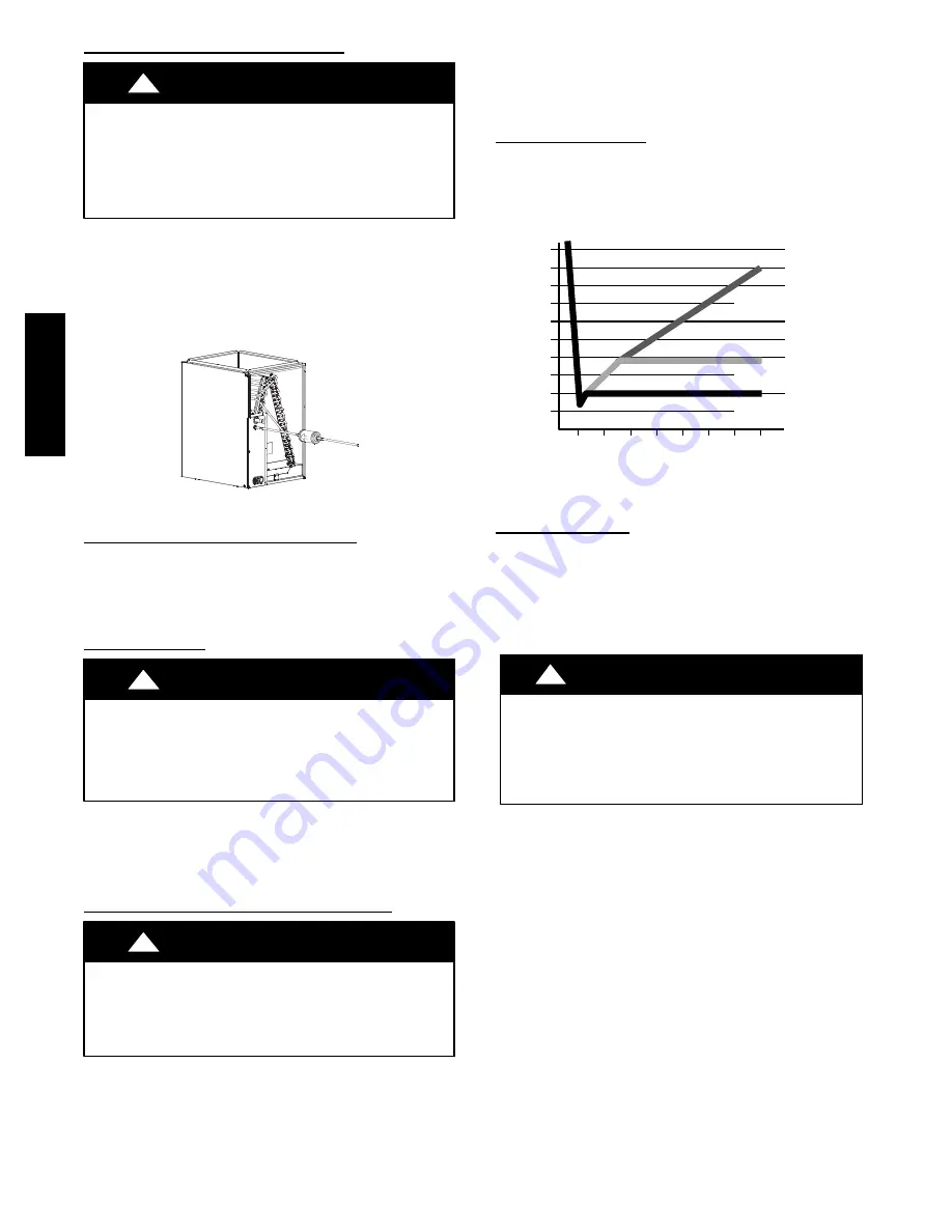
The deep vacuum method requires a vacuum pump capable of

pulling a vacuum of 500 microns and a vacuum gage capable of
accurately measuring this vacuum depth. The deep vacuum method

is the most positive way of assuring a system is free of air and
liquid water. (See Fig. 5)

500

MINUTES

0

1

2

3

4

5

6

7

1000

1500

LEAK IN

SYSTEM

VACUUM TIGHT

TOO WET
TIGHT

DRY SYSTEM

2000

MI

CRONS

2500

3000

3500

4000

4500

5000

A95424

A95424

Fig. 5 -- Deep Vacuum Graph

Final Tubing Check

IMPORTANT

: Check to be certain factory tubing on both indoor

and outdoor unit has not shifted during shipment. Ensure tubes are
not rubbing against each other or any sheet metal. Pay close
attention to feeder tubes, making sure wire ties on feeder tubes are
secure and tight.

Make Electrical Connections

!

WARNING

ELECTRICAL SHOCK HAZARD

Failure to follow this warning could result in personal injury

or death.
Do not supply power to unit with compressor terminal box

cover removed.

Be sure field wiring complies with local and national fire, safety,

and electrical codes, and voltage to system is within limits shown

on unit rating plate. Contact local power company for correction of
improper voltage. See unit rating plate for recommended circuit

protection device.

NOTE

: Operation of unit on improper line voltage constitutes

abuse and could affect unit reliability. See unit rating plate. Do not
install unit in system where voltage may fluctuate above or below
permissible limits.

NOTE

: Use copper wire only between disconnect switch and unit.

NOTE

: Install branch circuit disconnect of adequate size per NEC

to handle unit starting current. Locate disconnect within sight from
and readily accessible from unit, per Section 440--14 of NEC.

24AN

B

6

Summary of Contents for Infinity 24ANB6

Page 1: ...ult in enhanced installation reliability or operation WARNING ELECTRICAL SHOCK HAZARD Failure to follow this warning could result in personal injury or death Before installing modifying or servicing system main electrical disconnect switch must be in the OFF position There may be more than 1 disconnect switch Lock out and tag switch with a suitable warning label CUT HAZARD Failure to follow this c...

Page 2: ...t must be reinstalled before unit is placed into operation A11380 Fig 2 Louver Spacer Location Install on a Solid Level Mounting Pad If conditions or local codes require the unit be attached to pad tie down bolts should be used and fastened through knockouts provided in unit base pan Refer to unit mounting pattern in Fig 3 to determine base pan size and knockout hole location For hurricane tie dow...

Page 3: ...LINE APPLICATIONS Over 80 ft 24 38 m Crankcase Heater Yes Yes Compressor Start Assist Capacitor and Relay Yes Yes Evaporator Freeze Thermostat Yes For non Infinity systems only No Liquid Line Solenoid Valve No See Long Line Application Guideline Low ambient Pressure Switch Yes For non Infinity system only No Support Feet Recommended No Thermal Expansion Valve TXV Hard Shutoff Yes Yes Winter Start ...

Page 4: ...hould be evacuated using the recommended deep vacuum method of 500 microns An alternate triple evacuation method may be used See triple evacuation method in Service Manual IMPORTANT Always break a vacuum with dry nitrogen Deep Vacuum Method The deep vacuum method requires a vacuum pump capable of pulling a vacuum of 500 microns and a vacuum gage capable of accurately measuring this vacuum depth Th...

Page 5: ...sory transformer as required Final Wiring Check IMPORTANT Check factory wiring and field wire connections to ensure terminations are secured properly Check wire routing to ensure wires are not in contact with tubing sheet metal etc Compressor Crankcase Heater When equipped with a crankcase heater furnish power to heater a minimum of 24 hr before starting unit To furnish power to heater only set th...

Page 6: ...by subcooling method If any adjustment is necessary adjust charge slowly and allow system to operate for 15 minutes to stabilize before declaring a properly charged system If the indoor temperature is above 80_F 26 67_C and the outdoor temperature is in the favorable range adjust system charge by weight based on line length and allow the indoor temperature to drop to 80_F 26 67_C before attempting...

Page 7: ... the LED will be turned OFF until the next valid communication Amber Status Light An amber colored STATUS light is used to display the operation mode and fault codes as specified in the troubleshooting section See Table 3 for codes and definitions NOTE Only one fault code will be displayed on the outdoor unit control board the most recent with the highest priority Crankcase Heater Operation The cr...

Page 8: ... is ON when outdoor coil temp outdoor air temperature 25_F 3 89_C or outdoor coil temp 80_F 26 67_C or if outdoor fan has been OFF for 30 minutes Fan is turned on to allow refrigerant system to stabilize S Low pressure switch is ignored for first 3 minutes during low ambient start up After 3 minutes if LPS trips then outdoor fan motor is turned off for 10 minutes with the compressor running If LPS...

Page 9: ...three consecutive cycles then unit operation is locked out for 4 hours and the appropriate fault code See Table 3 is displayed CONTACTOR SHORTED DETECTION If there is compressor voltage sensed when there is no demand for compressor operation the contactor may be stuck closed The control will flash the appropriate fault code Check the contactor and control box wiring NO 230V AT COMPRESSOR If the co...

Page 10: ...not reading or out of range Ohm out sensor and check wiring Thermistors out of range 56 Improper relationship between coil sensor and outdoor air sensor Ohm out sen sors and check wiring Thermal Cutout 72 Compressor voltage sensed after start up then absent for 10 consecutive sec onds while cooling demand exists Possible causes are internal compressor over load trip or loss of high voltage to comp...

Page 11: ... Fig 10 Resistance vs Temperature Chart Outdoor Coil Temp OCT Outdoor Air Temp OAT COMM STATUS A06314 Fig 11 Single Stage Control Board LEGEND 24 V FACTORY WIRING 24 V FIELD WIRING FIELD SPLICE CONNECTION A10089 Fig 12 Infinity Control Four Wire Connection Wiring Diagrams See Thermostat Installation Instructions for specific unit combinations 24ANB6 ...

Page 12: ... operate CAUTION R R C W W1 Y Y2 G W Y C G R Y C 24VAC HOT 24VAC COM HEAT STAGE 1 HEAT STAGE 2 INDOOR FAN A C THERMOSTAT TYPICAL FURNACE or FAN COIL AIR CONDITIONER FIELD INSTALLED JUMPER WIRE R R C W W1 Y Y2 G W Y C G R Y C 24VAC HOT 24VAC COM HEAT STAGE 1 HEAT STAGE 2 INDOOR FAN A C THERMOSTAT TYPICAL FURNACE or FAN COIL AIR CONDITIONER A10091 LEGEND 24 V FACTORY WIRING 24 V FIELD WIRING FIELD S...

Page 13: ...manifold hose when charging into suction line with compressor operating S Manifold sets should be 700 psig high side and 180 psig low side with 550 psig low side retard S Use hoses with 700 psig service pressure rating S Leak detectors should be designed to detect HFC refrigerant S Puron refrigerant as with other HFCs is only compatible with POE oils S Vacuum pumps will not remove moisture from oi...

Page 14: ...W Morris St D Indianapolis IN 46231 Printed in U S A Edition Date 08 11 Manufacturer reserves the right to change at any time specifications and designs without notice and without obligations Catalog No 24ANB6 2SI Replaces 24ANB6 1SI 24ANB6 ...

Reviews: