background image


7


2.7.2 

B

URNER WITH 

O

UTDOOR 

C

OMBUSTION 

A

IR 

K

IT 

Certain burners are designed to function with combustion air 
taken directly from the outside. Follow the instructions provided 
with the burner, the fresh-air supply kit or the side-wall venting 
kit.


2.8 OIL 

TANK 

WARNING


Fire and explosion hazard. 


Use only approved heating type oil in this furnace. 
DO NOT USE waste oil, used motor oil, gasoline or 
kerosene. 


Use of these will result in death, bodily injury and/or 
property damage. 

CAUTION 


When a 0.75 USGPH or smaller nozzle is used, a 10 micron or 
finer filter, must be installed on the oil supply line to the 
furnace inside the building where the unit is located. 


This is a requirement in order for the heat exchanger warranty 
to remain in force. 
 
Check your local codes for the installation of the oil tank and 
accessories. 


At the beginning of each heating season or once a year, check 
the complete oil distribution system for leaks. 


Ensure that the tank is full of clean oil. Use No.1 or No.2 
Heating Oil (ASTM D396 U.S.) or in Canada, use No.1 or No.2 
Furnace Oil. 
A manual shut-off valve and an oil filter shall be installed in 
sequence from tank to burner. Be sure that the oil line is clean 
before connecting to the burner. The oil line should be 
protected to eliminate any possible damage. Installations 
where the oil tank is below the burner level must employ a two-
pipe fuel supply system with an appropriate fuel pump. A rise 
of 2.4 m (8') and more requires a two stage pump and a rise 
greater than 4.9 m (16') an auxiliary pump. Follow the pump 
instructions to determine the size of pipe needed in relation to 
the rise or to the horizontal distance. 

2.9 DUCTING 

WARNING 


Poisonous carbon monoxide gas hazard. 


DO NOT draw return air from inside a closet or utility 
room. Return air MUST be sealed to the furnace casing. 


Failure to properly seal ducts can result in death, bodily 
injury and/or property damage. 


The ducting must be designed and installed according to 
approved methods, local and national codes as well as good 
trade practices.  


When ducting supplies air to a space other than where the 
furnace is located, the return air must be sealed and also be 
directed to the space other than where the furnace is located. 


2.9.1 

A

IR FILTER


A properly sized air filter must be installed on the return air 
side of the unit. Refer to the Technical Specifications, 
table 7, for the correct dimensions. Also refer to the 
instructions supplied with the filter. 

2.9.2 

SUPPLY AIR ADJUSTMENT 

(4

 SPEED 

MOTOR

On units equipped with 4-speed blower motors, the supply 
air must be adjusted based on heating/air conditioning 
output and the static pressure of the duct system. For the 
desired air flow refer to the following table as well as the 
air flow tables based on static pressure in the Technical 
Specifications section of this manual. 

Table 1: Blower speed adjustments (heating mode, 4 

speed motor) 

HEATING 

CAPACITY 

(USGPH) 

STATIC 

PRESSURE 

(W.C.) 

RECOMMENDED 
BLOWER SPEED 

0.55 

0.25” MED-LOW 

0.55 

0.50” MED-LOW 

0.70 

0.25” MED-HIGH 

0.70 

0.50” HIGH 

Table 2: Blower speed adjustments (A/C mode, 4 

speed motor) 

A/C CAPACITY 

(TONS) 

RECOMMENDED 
BLOWER SPEED 

2.0 

MED-LOW 

2.5 

MED-HIGH 

3.0 

HIGH 


To effect the adjustment, the RED (for heating) and BLUE 
(for cooling and heat pump) wires can be changed on the 
motor. Also, refer to the position of the wires on the 
electronic board of the unit and consult the wiring 
diagrams. If the heating and air conditioning speeds are 
the same, the RED wire must be moved to “UNUSED 
LEADS” on the electronic board and the jumper provided 
with the BLUE wire must be used between the “HEAT” 
and “COOL” terminals. 


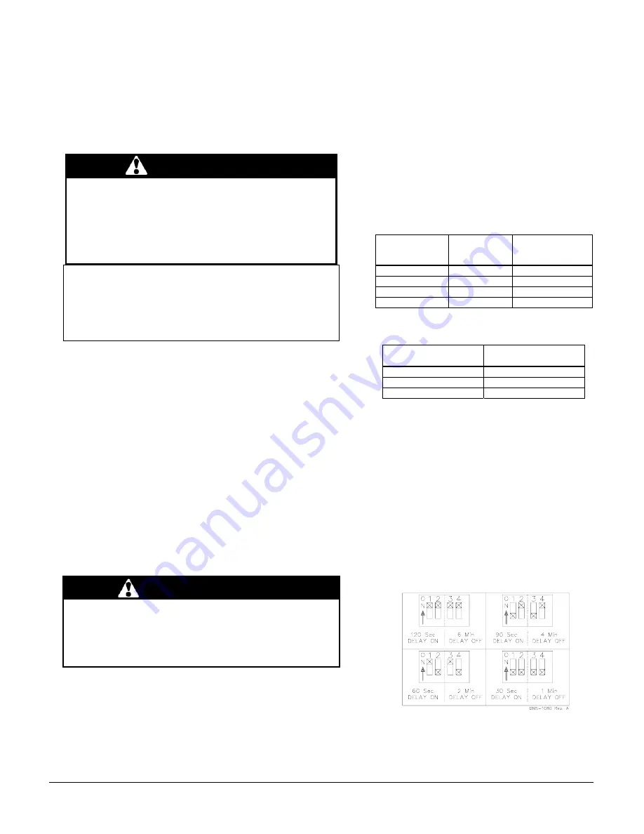
The blower start/stop delays can be adjusted by 
positioning the DIP switches on the electronic board as 
shown in the following figures. However, the 
recommended adjustments are 60 seconds blower ON 
delay and 2 minutes blower OFF delay. 

Figure 5: Blower start / stop delays - Board #1158 


2.10 

SUPPLY AIR ADJUSTMENT (ECM 
VARIABLE SPEED MOTORS) 

On units equipped with ECM variable speed blower 
motors, the air supply must be adjusted based on 

Summary of Contents for OBL098

Page 1: ... Keep this booklet of information for future reference SERVICER Use the information in this booklet to service the appliance and affix the booklet adjacent to the appliance after servicing ama B140 4 UL727 Copyright 2009 CAC BDP D 7310 W Morris St D Indianapolis IN 46231 Printed in U S A Edition Date 03 13 Manufacturer reserves the right to change at any time specifications and designs without not...

Page 2: ...R SPEED ADJUSTMENTS HEATING MODE 4 SPEED MOTOR 7 TABLE 2 BLOWER SPEED ADJUSTMENTS A C MODE 4 SPEED MOTOR 7 TABLE 3 HEATING MODE 8 TABLE 4 AIR CONDITIONING MODE 8 TABLE 5 CFM ADJUSTMENT ALL MODES 8 TABLE 6 DELAY ADJUSTMENTS HEATING MODE 8 TABLE 7 TECHNICAL SPECIFICATIONS 13 TABLE 8 AIRFLOW DATA MODELS WITH 1 2 HP ECM MOTORS 14 TABLE 9 AIRFLOW DATA MODELS WITH 1 3 HP PSC MOTORS 15 TABLE 10 MINIMUM C...

Page 3: ...nformation such as the model and serial numbers of the furnace WARNING Installations and repairs performed by unqualified persons can result in hazards to them and to others Installations must conform to local codes or in the absence of same to codes of the country having jurisdiction The information contained in this manual is intended for use by a qualified technician familiar with safety proced...

Page 4: ... be installed in an area where the ambient and return air temperatures are above 15 C 60 F In addition the furnace should be installed as closely as possible to the vent so that the connections are direct and kept to a minimum The heater should also be located close to the centre of the air distribution system 2 1 1 INSTALLATION IN AN ENCLOSURE The unit can be installed in an enclosure such as a c...

Page 5: ...ional final adjustments will be required Refer to section 3 of this manual 2 4 3 POST PURGE DELAY ADJUSTMENT The post purge delay on the oil fired burners is factory set to zero second This delay is applicable for all installations with chimney venting For heating units installed with side wall venting and a burner equipped with this feature the post purge delay must be set to 15 seconds No delay ...

Page 6: ...urner must shut off immediately while the blower continues to run to the end of the cool down cycle If the test is not in line with the above call a QUALIFIED SERVICE TECHNICIAN 2 7 COMBUSTION AIR SUPPLY AND VENTILATION WARNING Poisonous carbon monoxide gas hazard Comply with NFPA 31 U S and CSA B139 Canada standards for the installation of Oil Burning Equipment and applicable provisions of local ...

Page 7: ... must be designed and installed according to approved methods local and national codes as well as good trade practices When ducting supplies air to a space other than where the furnace is located the return air must be sealed and also be directed to the space other than where the furnace is located 2 9 1 AIR FILTER A properly sized air filter must be installed on the return air side of the unit Re...

Page 8: ... to activate a switching relay Also refer to the instructions supplied with the accessory 2 11 2 ELECTRONIC AIR CLEANER EAC The EAC terminal on the electronic board supplies 120 VAC when the blower is operating in the heating or air conditioning mode This signal can be used to activate an electronic air cleaner that is not equipped with an air flow switch If the cleaner is equipped with an air flo...

Page 9: ...tion side of the oil piping and pump Slowly close and tighten the bleed screw Once closed the flame will light up 3 3 2 PRESSURE ADJUSTMENT The oil pressure must be adjusted according to the Technical Specifications of this manual An adjustment screw and a connection for a pressure gauge are located on the oil pump for that purpose Also refer to the burner instruction manual 3 3 3 COMBUSTION CHECK...

Page 10: ...eed investigate for ductwork obstructions dirty or improper air filter improper firing caused by improper pump pressure or nozzle sizing 3 3 8 LIMIT CONTROL CHECK After operating the furnace for at least 15 minutes restrict the return air supply by blocking the filters or the return air register and allow the furnace to shut off on High Limit The burner will shut off but the blower will continue t...

Page 11: ...ssembly cover 3 Remove the cover 4 Remove the two screws holding the control box to the heat transfer tube assembly Sliding the control box in the appropriate direction will unlock it from the heat transfer tube assembly 5 Carefully remove any build up from the thermal switch surface CAUTION Do not dent or scratch the surface of the thermal switch If the thermal switch is damaged it MUST be replac...

Page 12: ...rvice telephone Day Night Dealer name and address START UP RESULTS Nozzle Pressure lb po 2 Burner adjustments Primary air Fine air Drawer Assembly CO2 Smoke scale Bacharach Gross stack temperature F Ambient temperature F Chimney draft W C Overfire draft W C Test performed by ...

Page 13: ...lator damper 0 3 5 1 5 25 0 3 5 1 5 25 AFUE From CSA B212 standard and Canadian regulation 87 1 85 4 87 1 85 4 AFUE From ASHRAE 103 standard and US regulation 86 7 85 0 86 7 85 0 Volts Hertz Phase Rated current Amps Minimum ampacity for wire sizing Amps Max fuse size Amps Control transformer VA External control power available Heating VA Cooling VA Heating blower speed at 0 25 W C SP MED LOW MED H...

Page 14: ...ec 13 60 sec 38 3 min D 1 ON 2 ON All 13 30 sec 100 0 sec 100 2 min No adjustment required A C size PreRun On Delay CFM Level Time ShortRun On Delay CFM Level Time Off Delay CFM Level Time All No Delay No Delay 100 90 sec in the air distribution system Alternate position for 0 55 input In Cooling Dehumidification mode with no 24 VAC input to DH the CFMs are reduced by 15 The CFMs shown are reduced...

Page 15: ...AMT098 EXTERNAL STATIC PRESSURE WITH AIR FILTER Table 10 Minimum clearances from combustible material LOCATION APPLICATIO N CLEARANCES com bustible m aterials RECOMMANDED ACCESS FOR SERVICE FURNACE 1 24 SUPPLY PLENUM WITHIN 6 FEET OF FURNACE 1 BACK ACCESS PANEL TO BLOWER 4 24 FURNACE OR PLENUM 2 HORIZONTAL WARM AIR DUCT WITHIN 6 FEET OF FURNACE 2 BO TTOM FURNACE COMBUSTIBLE FLO OR 0 FLUE PIPE ARO ...

Page 16: ...16 Figure 6 Furnace Dimensions ...

Page 17: ...17 Figure 7 Wiring Diagram 4 Speed Motor PSC ...

Page 18: ...18 Figure 8 Wiring Diagram Variable Speed Motor ECM ...

Page 19: ...19 Figure 9 Parts List With 4 Speed motor PSC B50082E ...

Page 20: ... SHUT OFF BVSO 225 A 34 B03567 BAFFLE 35 B03587 CLEAN OUT ASSEMBLY 36 B03574 PROTECTION COVER ASSEMBLY 37 F07F011 HEX NUT 3 8 16NC ZINC 38 Z99F061 SIGHT GLASS FOR HEAT EXCHANGER 39 F06F015 ZINC WASHER 1 7 16 M20 40 B03554 WIRE CHANEL 41 L04I010 STRAIN REL BUSHING 42 B03573 FRONT PANEL ASSEMBLY Includes panel insulation observation door gasket 43 B03590 FRONT PANEL INSULATION 44 L07F003 ROCKER SWIT...

Page 21: ...21 Figure 10 Parts List With variable speed motor ECM B50083E ...

Page 22: ...001 BLOCKED VENT SHUT OFF BVSO 225 A 34 B03567 BAFFLE 35 B03587 CLEAN OUT ASSEMBLY 36 B03574 PROTECTION COVER ASSEMBLY 37 F07F011 HEX NUT 3 8 16NC ZINC 38 Z99F061 SIGHT GLASS FOR HEAT EXCHANGER 39 F06F015 ZINC WASHER 1 7 16 M20 40 B03554 WIRE CHANEL 41 L04I010 STRAIN REL BUSHING 42 B03573 FRONT PANEL ASSEMBLY Includes panel insulation observation door gasket 43 B03590 FRONT PANEL INSULATION 44 B03...

Page 23: ......

Page 24: ......

Page 25: ...RRET BVSO 225 A 34 B03567 DEFLECTEUR 35 B03587 ASS BRIDE DE NETTOYAGE 36 B03574 ASS COUVERCLE DE PROTECTION 37 F07F011 ECROU HEXAGONAL 3 8 16NC ZINC 38 Z99F061 OEIL DE REGARD POUR ECHANGEUR 39 F06F015 RONDELLE ZINC 1 7 16 M20 40 B03554 CACHE FIL 41 L04I010 CONNECTEUR PRESSION 42 B03573 ASS PANNEAU AVANT Comprend panneau isolation et garniture de porte 43 B03590 ISOLATION PANNEAU AVANT 44 B03555 PR...

Page 26: ...____________________________________________________________________________________ 23 Figure 10 Liste de pièces Avec moteur vitesse variable ECM B50083E ...

Page 27: ...3567 DEFLECTEUR 35 B03587 ASS BRIDE DE NETTOYAGE 36 B03574 ASS COUVERCLE DE PROTECTION 37 F07F011 ECROU HEXAGONAL 3 8 16NC ZINC 38 Z99F061 OEIL DE REGARD POUR ECHANGEUR 39 F06F015 RONDELLE ZINC 1 7 16 M20 40 B03554 CACHE FIL 41 L04I010 CONNECTEUR PRESSION 42 B03573 ASS PANNEAU AVANT Comprend panneau isolation et garniture de porte 43 B03590 ISOLATION PANNEAU AVANT 44 L07F003 COMMUT BASC SPST 45 B0...

Page 28: ...____________________________________________________________________________________ 21 Figure 9 Liste de pièces Avec moteur 4 vitesses PSC B50082E ...

Page 29: ...Figure 8 Diagramme électrique Moteur vitesse variable ECM 20 ...

Page 30: ...Figure 7 Diagramme électrique Moteur 4 vitesses PSC ____________________________________________________________________________________ 19 ...

Page 31: ...Figure 6 Dimensions de la fournaise 18 ...

Page 32: ...PLICATION DÉGAGEMENTS matériaux combustibles ACCÈS RECOMMANDÉ POUR L ENTRETIEN FOURNAISE 2 54 cm 1 0 6 m 24 PLÉNUM D ALIMENTATION JUSQU À 1 8m 6 DE LA FOURNAISE 2 54 cm 1 ARRIÈRE PORTE D ACCÈS AU VENTILATEUR 10 16 cm 4 0 6 m 24 FOURNAISE OU PLÉNUM 5 08 cm 2 HORIZONTALE À LA CONDUITE PREMIERS 1 8m 6 5 08 cm 2 DESSOUS FOURNAISE PLANCHER COMBUSTIBLE 0 cm 0 CONDUIT DE RACCORDEMENT AUTOUR DU CONDUIT DE...

Page 33: ... 100 2 min Pas d ajustement requis Capacité climatisation PreRun Délai On Niveau PCM Temps ShortRun Délai On Niveau PCM Temps Délai Off Niveau PCM Temps Tout Aucun délai Aucun délai 100 90 sec Ajustement alternatif pour la puissance de 0 55 USGPH TABLEAU DE DÉLAIS POUR MODE CHAUFFAGE AU MAZOUT PreRun et ShortRun représentent les périodes de temps que le ventilateur part à très bas PCM pour minimis...

Page 34: ...s 87 1 85 4 87 1 85 4 AFUE À partir du standard ASHRAE 103 et des lois américaines 86 7 85 0 86 7 85 0 Volts Hertz Phase Consommation Amp Amp minimum pour grosseur du fil Amp Fusible max Amp Contrôle du transformateur VA Courant disponible contrôles externes Chauffage VA Climatisation VA Vitesse du ventilateur à une pression statique de 0 25 W C PS MED LOW MED HIGH Vitesse du ventilateur à une pre...

Page 35: ... du technicien de service RÉSULTAT DU TEST DE MISE EN MARCHE Gicleur Pression lb po 2 Ajustements du brûleur Bande principale Bande fine Position de la tête CO 2 Indice de fumée Bacharach Température des gaz à la sortie de l unité F Température ambiante F Tirage dans la cheminée W C Tirage ou pression au dessus du feu W C Examiné par ...

Page 36: ...er le boîtier de commande à l aide des 2 vis qui avait été enlevées à l étape 4 8 Remettre en place le couvercle de l ensemble avec les vis enlevées à l étape 2 9 Remettre l alimentation électrique 4 3 NETTOYAGE DE LA TÊTE DU BRÛLEUR Une fois par année retirer l assemblage de la ligne d huile et des électrodes du brûleur Nettoyer la tête de rétention et les électrodes si nécessaire Nettoyer aussi ...

Page 37: ...te de la combustion après chaque entretien annuel Ne pas tenter de réparer l unité ou les contrôles de l appareil Appeler un technicien qualifié Avant d appeler pour un service de réparation vérifier les points suivants 1 Vérifier le niveau de mazout du réservoir et si le robinet d arrêt est ouvert 2 Vérifier les fusibles et disjoncteur 3 Vérifier si l interrupteur d alimentation principal de la f...

Page 38: ...lateur de tirage barométrique fourni avec l appareil Pour que ce régulateur fonctionne correctement monter les goupilles pins à l horizontale et le devant du régulateur à la verticale voir les instructions incluses avec le régulateur Ajuster le régulateur de tirage après que l appareil ait fonctionné au moins cinq minutes et réglé entre 0 025 et 0 060 W C 3 3 5 Test de pression dessus feu La press...

Page 39: ...êt du ventilateur sont réglés de façon satisfaisante 9 Le thermostat de la pièce est en mode chauffage et est réglé à une température supérieure à la température ambiante Pour démarrer l unité mettre l interrupteur électrique principal à ON 3 2 SÉQUENCE DE FONCTIONNEMENT EN MODE CHAUFFAGE AU MAZOUT 1 Le contact W R du thermostat ferme 2 Le moteur du brûleur démarre pour faire un conditionnement de...

Page 40: ...0 0 ON OFF B 10 10 OFF ON C 10 10 ON ON D N A 0 Tableau 6 Ajustement des délais en mode chauffage SW4 Delay Délai Position interrupteurs DIP 1 2 POSITION Puissance USGPH OFF OFF A 0 70 ON OFF B 0 55 OFF ON C 0 55 ON ON D ALL Position alternative pour la puissance 0 55 USGPH 2 12 INSTALLATION D ÉQUIPMENTS CONNEXES MISE EN GARDE Risque de décharge électrique Interrompre le courant électrique OFF au ...

Page 41: ... placard ou une salle de rangement Le conduit de retour d air DOIT être étanche sur la fournaise Le fait de ne pas avoir de conduits étanches peut entraîner la mort des blessures et ou des dommages matériels Construire et installer le système de distribution d air conformément aux méthodes approuvées et conformément aux codes locaux et nationaux Lorsque les conduits d alimentation d air transporte...

Page 42: ...sionner une flamme malpropre des odeurs dans la maison le refoulement des appareils de combustion et peut entraîner des nausées l asphyxie et ou la mort des occupants L appareil de chauffage central nécessite un approvisionnement adéquat en air de combustion Il est fréquent de considérer que les vieilles maisons comportent suffisamment d infiltrations d air pour combler les besoins en air de combu...

Page 43: ... évacuation Cependant un volet motorisé à fonctionnement automatique approuvé par une agence certifiée peut être installé si désiré Suivre les instructions d installation fournies avec le volet motorisé Si cette fournaise ou d autres appareils ne sont pas adéquatement évacués cela peut entraîner la mort ou des dommages corporels et ou matériels Pour assurer un fonctionnement sécuritaire et satisfa...

Page 44: ...ls d origine de l appareil de chauffage central utilisez seulement du fil de cuivre résistant à la même température que les fils d origine 2 3 INSTALLATION DU THERMOSTAT L installation d un thermostat de contrôle de la température de l espace à chauffer est obligatoire Suivre les instructions d installation incluses avec le thermostat Consulter aussi les diagrammes électriques fournis avec les ins...

Page 45: ...t être utilisée 2 1 EMPLACEMENT MISE EN GARDE Risque d incendie ou d explosion L appareil doit être installé au niveau Ne jamais installer avec une inclinaison vers l avant Ne pas ranger ou utiliser d essence ou toutes autres substances inflammables à proximité de l appareil Ne pas se conformer à ces instructions pourrait entraîner la mort ou des dommages corporels et ou matériels AVERTISSEMENT Ce...

Page 46: ...comment le changer une fois par année iv Le filtre à air comment le changer vérifier mensuellement et nettoyer ou changer si nécessaire g Avant d appeler pour le service prendre en note les renseignements sur la page 14 de ce manuel pour le numéro du modèle et le numéro de série de la fournaise MISE EN GARDE L installation ou les réparations par du personnel non qualifié peuvent entraîner des risq...

Page 47: ...VERTURE DE VENTILATION DANS LA PORTE DU PLACARD 4 F IGURE 2 B RANCHEMENT DU THERMOSTAT C HAUFFAGE ET CLIMATISATION U NITÉ AVEC MOTEUR 4 VITESSES 5 F IGURE 3 B RANCHEMENT DU THERMOSTAT C HAUFFAGE ET C LIMATISATION U NITÉ AVEC MOTEUR ECM 5 F IGURE 4 B RANCHEMENT DU THERMOSTAT C HAUFFAGE ET CLIMATISATION T HERMOPOMPE U NITÉ AVEC MOTEUR ECM 5 F IGURE 5 D ÉLAIS DE DÉPART ET D ARRÊT DU VENTILATEUR C ART...

Page 48: ...EUR Conserver ce manuel d information pour références ultérieures TECHNICIEN DE SERVICE Utiliser l information contenue dans ce manuel afin d effectuer l entretien de l appareil Garder ce manual près de l unité pour références ultérieures ama B140 4 UL727 Copyright 2009 CAC BDP D 7310 W Morris St D Indianapolis IN 46231 Printed in Canada Edition Date 03 13 Le manufacturier se réserve le droit de m...

Reviews: