7–25
T-340
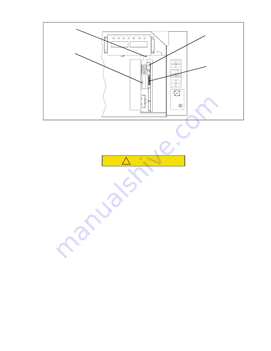
Figure 7.16 Controller Section of the Control Box
1) Controller Software Programming Port
2) Mounting Screw
3) Controller
4) Test Points
- - - - -
7.23.3
Controller Programming Procedure
CAUTION
!
The unit must be OFF whenever a programming card is inserted or removed from the controller
programming port.
1. Turn unit OFF, via start-stop switch (ST).
2. Insert software/programming PCMCIA card containing the following (example) files into the programming/
software port (see
):
menuDDMM.ml3
, this file allows the user to select a file/program to upload into the controller.
cfYYMMDD.ml3
, multi-configuration file.
3. Turn unit ON, via start-stop switch (ST).
Procedure for Software Versions prior to 5328 and/or Cards Without Updated Menu Option (menu0111.ml)
a. Procedure for Loading Operational Software:
1. The display module will display the message ruN COnFG. (If a defective card is being used the display will
blink the message “bAd CArd.” Turn start-stop switch OFF and remove the card.)
2. Press the Up or Down Arrow key until the display reads, LOAd 53XX for Scroll.
3. Press the ENTER key on the keypad.
4. The display will alternate to between PrESS EntR and rEV XXXX.
5. Press the ENTER key on the keypad.
6. The display will show the message “Pro SoFt”. This message will last for up to one minute.
7. The display module will go blank briefly, then read “Pro donE” when the software loading has completed. (If
a problem occurs while loading the software: the display will blink the message “Pro FAIL” or “bad 12V.”
Turn start-stop switch OFF and remove the card.)
8. Turn unit OFF, via start-stop switch (ST).
9. Remove the PCMCIA card from the programming/software port and return the unit to normal operation by
placing the start-stop switch in the ON position.


