3–3
T-340
The evaporator fans circulate air through the container by pulling it in the top of the unit, directing it through the
evaporator coil, where it is heated or cooled, and discharging it at the bottom.
If the unit is equipped with eAutoFresh, system components are mounted in addition to the standard refrigeration
unit components. The stepper motor component is installed in the vent; the air filter, CO
2
sensor, stepper motor
drive and CO
2
sensing lines are installed on the rib of the upper grill.
Most evaporator components are accessible by removing the upper rear panel or by removing the evaporator fan
, Items 1 and 19).
3.1.4
Compressor Section
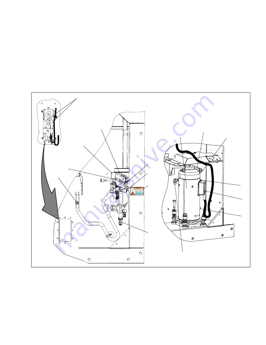
The compressor section (see
) includes the compressor, digital unloader valve (DUV), high pressure
switch, discharge pressure transducer (DPT), evaporator pressure transducer (EPT) and the suction pressure
transducer (SPT). The supply temperature sensor (STS), supply recorder sensor (SRS), and ambient sensor are
located to the left of the compressor.
Figure 3.3 Compressor Section
1) Compressor
2) Discharge Temperature Sensor (CPDS) location
3) Discharge Connection
4) Suction Connection Location
5) Compressor Terminal Box
6) Oil Drain location
7) Economizer Connection
8) Discharge Pressure Transducer (DPT)
9) Suction Pressure Transducer (SPT)
10) Digital Unloader Valve (DUV)
11) Evaporator Pressure Transducer (EPT)
12) Discharge Service Valve
13) High Pressure Switch (HPS)
14) Warning Label
15) Suction Service Valve
16) Supply Temperature Sensor (STS) / Supply
Recorder Sensor (SRS)
- - - - -
2


