33
TROUBLESHOOTING SUPPLY FAN MOTOR OVER
-
LOAD TRIPS
The supply fan used in 50TC units is a forward-curved centrifu
-
gal wheel. At a constant wheel speed, this wheel has a character
-
istic that causes the fan shaft load to DECREASE when the stat
-
ic pressure in the unit-duct system increases and to INCREASE
when the static pressure in the unit-duct system decreases (and
fan airflow rate increases). Motor overload conditions typically
develop when the unit is operated with an access panel removed,
with unfinished duct work, in an economizer-open mode, or a
leak develops in the duct system that allows a bypass back to
unit return opening.
CONDENSER FAN MOTOR PROTECTION
The condenser fan motor is internally protected against
overtemperature.
Control Circuit, 24v
The control circuit is protected against overcurrent conditions by a
circuit breaker mounted on the control transformer TRAN. Reset
is manual.
The factory-installed PremierLink Controller includes the supply-
air temperature (SAT) sensor. The outdoor air temperature (OAT)
sensor is included in the FIOP/accessory EconoMi$er 2 package.
NOTE: Refer to PremierLink Installation, Start-Up and Configu
-
ration Instructions. Have a copy of this manual available at unit
start-up.
PremierLink™ Control
For details on operating units equipped with the factory-installed
PremierLink controller option, refer to the
PremierLink Retrofit
Rooftop Controller Version 3.x Installation, Start-Up, and Config
-
uration Instructions
manual.
RTU Open Control System
For details on operating units equipped with the factory-installed
RTU Open controller, refer to the
Factory-Installed RTU Open
Multi-Protocol Controller Control, Start-Up, Operation and Trou
-
bleshooting
manual.
ECONOMI$ER SYSTEMS
The 50TC units may be equipped with a factory-installed or acces
-
sory (field-installed) EconoMi$er system. Three types are avail
-
able: with a logic control system (EconoMi$er IV and
EconoMi$er X) and without a control system (EconoMi$er2). See
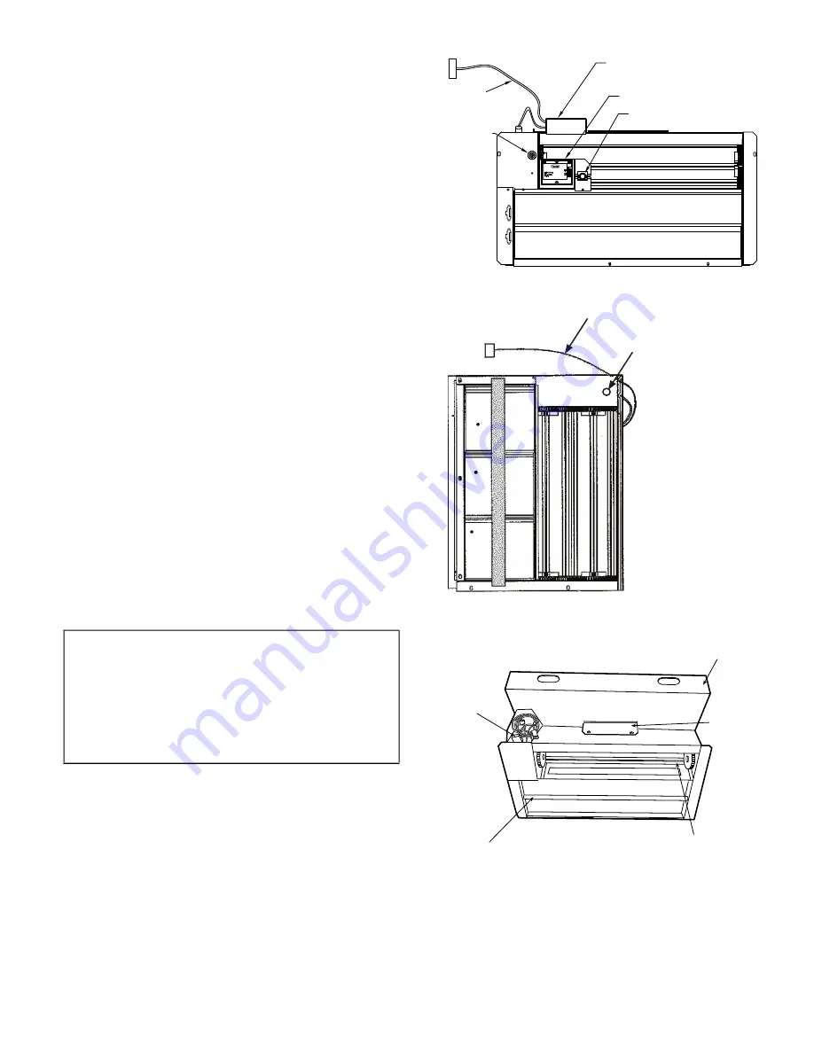
Fig. 45-47 for component locations on each type. The W7212
controller is used for EconoMi$er IV and the W7220 controller is
used for EconoMi$er X. See Fig. 48-51 for EconoMi$er section
wiring diagrams.
All three EconoMi$er system use direct-drive damper actuators.
Fig. 45 —
EconoMi$er IV Component Locations
Fig. 46 —
EconoMi$er X Component Locations
Fig. 47 —
EconoMi$er 2 Component Locations
IMPORTANT: Any economizer that meets the economizer re
-
quirements as laid out in California’s Title 24 mandatory sec
-
tion 120.2 (fault detection and diagnostics) and/or prescriptive
section 140.4 (life-cycle tests, damper leakage, 5 year warranty,
sensor accuracy, etc), will have a label on the economizer. Any
economizer without this label does not meet California’s
Title 24. The five-year limited parts warranty referred to in sec
-
tion 140.4 only applies to factory installed economizers. Please
refer to the economizer on the unit.
ECONOMI$ER IV
CONTROLLER
OUTSIDE AIR
TEMPERATURE SENSOR
LOW AMBIENT
SENSOR
ACTUATOR
WIRING
HARNESS
OUTSIDE AIR
TEMPERATURE SENSOR
WIRING HARNESS
ECONOMI$ER2
PLUG
BAROMETRIC
RELIEF
DAMPER
OUTDOOR
AIR HOOD
HOOD
SHIPPING
BRACKET
GEAR DRIVEN
DAMPER
Summary of Contents for WeatherMaker 50TC 17-30 Series
Page 34: ...34 Fig 48 RTU Open Overlay for Economizer Wiring ...
Page 35: ...35 Fig 49 VFD Overlay for W2770 Controller Wiring ...
Page 80: ...80 Fig C 50TC 17 28 Control Wiring Diagram APPENDIX D WIRING DIAGRAMS ...
Page 81: ...81 Fig D 50TC 30 Control Wiring Diagram 208 230 3 60 Units APPENDIX D WIRING DIAGRAMS ...
Page 82: ...82 Fig E 50TC 30 Control Wiring Diagram 460 3 60 575 3 60 Units APPENDIX D WIRING DIAGRAMS ...
Page 83: ...83 Fig F 50TC 17 30 Power Wiring Diagram 208 230 3 60 Units APPENDIX D WIRING DIAGRAMS ...
Page 84: ...84 Fig G 50TC 17 30 Power Wiring Diagram 460 3 60 575 3 60 Units APPENDIX D WIRING DIAGRAMS ...
Page 89: ...89 Fig L 50TC PremierLink System Wiring Diagram APPENDIX D WIRING DIAGRAMS ...
Page 90: ...90 Fig M 50TC RTU Open Wiring Diagram APPENDIX D WIRING DIAGRAMS ...
Page 91: ...91 Fig N 50TC SAV VFD System Wiring Diagram APPENDIX D WIRING DIAGRAMS ...
Page 93: ......


