background image

Collimation of the Optics:

The internal optics of the telescope have already been “collimated” or 

“aligned” at the factory.  However, rough handling of the telescope may 

knock the optics out of collimation, resulting in poor optical performance.  

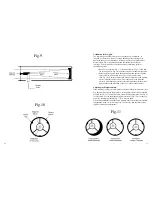
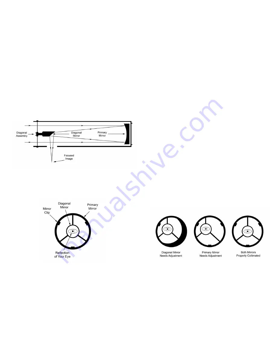
Please refer to Fig. 9 to better understand the internal layout of your  

telescope.  To determine if your telescope needs collimation perform  

the following steps:


•  Remove the eyepiece (Fig. 1-3) from the focuser (Fig. 1-2) and turn 

the focusing knob (Fig. 1-4) until the tube is at its innermost position.  


•  Point the telescope at a plain background and then peer through the 

empty focuser.  You should see a series of concentric circles  

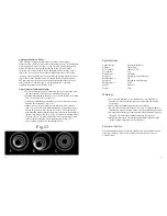
(See Fig. 10).  The outer most circle being a reflection of the primary 

mirror (with three mirror clips).  The inner circle is the diagonal 


mirror, which should be precisely centered inside the primary mirror.  

You should see the reflection of your eye in the diagonal mirror.

Adjusting the Diagonal Holder:

If the telescope is properly collimated you should see the primary mirror (See 

Fig. 10) and three clips in their entirety.  If the primary mirror is not centered 

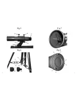
properly (See Fig. 11) you will need to adjust the diagonal mirror (See Fig. 9) 

to correct this.  Loosen the diagonal mirror tilt screws (Fig. 7-26) so that you 

can move the diagonal holder (Fig. 7-27) with your hand.  


Tilt the diagonal holder until the entire primary mirror is visible and carefully 

retighten the screws to lock it into place.  If necessary, turn the three screws 

slightly to make fine adjustments.  

15

14

Fig.10

Fig.11

Fig.9

Summary of Contents for RP-100

Page 1: ...PTICAL HAUPPAUGE NY 11788 www carsonoptical com MADE IN TAIWAN 2010 CARSON OPTICAL HAUPPAUGE NY 11788 www carsonoptical com MADE IN CHINA 2011 CARSON OPTICAL HAUPPAUGE NY 11788 www carsonoptical com M...

Page 2: ...ronomers looking to explore the wonders of outer space and the world around them Please read this man ual carefully to ensure that you assemble and use your telescope correctly When used properly your...

Page 3: ...Fig 1 Fig 3 Fig 2 5 4 Fig 4...

Page 4: ...Fig 6 Fig 5 Fig 7 7 6 Fig 8...

Page 5: ...with the ground You will notice there are holes in the tripod leg braces Fig 6 22 These are designed to hold eyepieces when not in use Attaching the U Mount Remove the U mount Fig 1 6 from the box Pla...

Page 6: ...nob Fig 5 17 until the image in the finder scope is sharp and clear Check the alignment at nighttime by repeating this process with a bright star or the moon Make any necessary adjustments Now that yo...

Page 7: ...There are many conditions that may affect your ability to focus or observe celestial objects clearly Brightly lit areas light pollution will make it difficult to see faint objects in the sky It will...

Page 8: ...The outer most circle being a reflection of the primary mirror with three mirror clips The inner circle is the diagonal mirror which should be precisely centered inside the primary mirror You should...

Page 9: ...need to make adjustments to the primary mirror Loosen the primary mirror locking screws Fig 8 28 and use the horizontal and altitude adjustments to move the circles to the edge of the telescope field...

Page 10: ...f an implied warranty and or do not allow excluding or limiting incidental or consequential damages If so the above limitations or exclusions may not apply to you Warranty Procedure Provide proof of p...

Reviews: