background image

12 

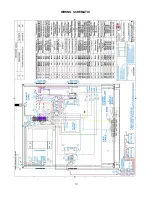
WIRING DIAGRAM & PARTS LIST 

Part Number  Description 
18100-0159 

Locking Spring Plunger 

18301-5284


6” Red Rigid Caster 

18301-5293


6” Red Swivel Caster with Brake 

18301-8321


Threaded Stem Ball Caster 

18302-0110


Link Lock Spring 

18303-0082


Snap-in Pocket Pull 

18312-0671 

Battery Compartment Overlay 

18312-0673 Control 

Overlay 

18600-0142 

275F Hi-Limit-Auto QC Gold 

18602-0309 

Fuse 16 Amp, 400VDC, 5x20mm 

18602-0312 

Fuse Holder, 16A, 32VDC 

18602-0317 

Class - Fuse, 50A 

18602-0318 

Fuse Holder, Class-T 300V 

18602-0319 

Relay-24VDC Coil, 30A cont. 

18603-0004 Wiring 

Kit 

18603-0006 

3’ Patch Cord 

18603-0007 

AC Detection Cord 

18603-5018

 Fan 

Blade 

1300W, 120V, 

10.8A, 60Hz, single 

phase, NEMA 5-20P 

Part Number  Description 

18605-0017


14/3 HSJO Cord w/ 5-20 Plug 

18607-0019 

Terminal Block 6 pos. #603 

18612-0162 

Hoop Element #1 400W 

18612-0163 

Hoop Element #2 400W 

18614-0272 

Fan Guard, #SC120-W15 

18614-0275


Fan Guard, #SC80-W2 

18614-0303 

Muffin Fan, 24VDC, 26 CFM 

18614-0392 

Blower Motor, 24VDC, 1500 RPM 

18614-0393 

4.72”x1.57” 24VDC 105 CFM 

18616-0399 

Xantrex C40 CHRG Controller 

18616-0401 

12V, 540WPC 155AH Battery 

18616-0402 

Gridless Hot Display Board 

18616-0404 

Gridless Hot Power Board 

18616-0405 Thermistor, 50K, 4” Probe 
18616-0406 

Blocking Diode, 600V, 70A 

18616-0408 

Power Converter, 1200W, 30VDC 

18616-9998

 Cord 

Grip 

29034-0282

 Silicone 

Sponge 

NOTE:


The technical content of this manual, including any wir-
ing diagrams, schematics, parts breakdown illustrations 
and / or adjustment procedures, is 

intended for use 

ONLY by qualified technical personnel

NOTE:  


For warranty service, call Carter-Hoffmann direct at 800-
323-9793 for authorization, we will dispatch the nearest 
authorized service agency. 

Summary of Contents for GTH12

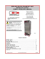
Page 1: ...ation Instructions are read and followed Damage to the appliance may occur if these in structions are not followed This manual is considered to be a permanent part of this appliance This manual must r...

Page 2: ...or its agents When battery reaches 0 it is no longer safe to hold potentially hazardous foods Cleanliness of this appliance is essential to good sanitation Read and follow all included cleaning instru...

Page 3: ...the skin wash immediately and thoroughly If electrolyte enters the eyes also seek medical attention Neutralize spilled electrolyte with a solution of 1 lb bicarbonate of soda baking soda to one gallo...

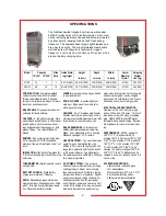
Page 4: ...rsal tray slides Fully adjustable at 1 3 4 spacing Standard spacing at 3 1 2 centers HEATING SYSTEM Top mounted blower heater for even heat distribution High efficiency DC motor with cooling fans Full...

Page 5: ...r the appliance is properly grounded Unpack the cart and heating unit Ensure that all packing materials and protective plastic has been removed from the unit Inspect all components for completeness an...

Page 6: ...ZARD Allow the unit to cool before performing any cleaning or maintenance procedures WARNING ELECTRIC SHOCK HAZARD DO NOT spray or splash water on the heater con trol panel timer or wiring IMPORTANT C...

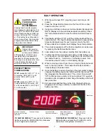
Page 7: ...y will show cabinet temperature setting Press the Temperature Button to view the actual cabinet tempera ture 4 The display will show PrE until the unit has reached the de sired set point Pre heat to d...

Page 8: ...cants for stainless steel products Do not use oil PERIMETER BUMPERS Vinyl which has been dislodged from the channel due to severe bumping or scraping can be pried back into place with a common screwdr...

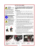
Page 9: ...Fig 1 on the left and right sides of the battery tray towards the center of the cart Twist the knobs one quarter turn until they remain in the out unlocked position 4 Pull the battery tray away from t...

Page 10: ...y tray towards the center of the cart Twist the knobs one quar ter turn until they remain in the out unlocked position Fig 1 4 Pull the battery tray away from the cart using the formed met al handle i...

Page 11: ...ORE PERFORMING THESE PROCEDURES CABINET MUST BE COOL AND ALL FOOD MUST BE RE MOVED INSTALLATION CONTINUED 12 Next twist the knobs one quarter turn until they release from the out unlocked position Fig...

Page 12: ...20 Plug 18607 0019 Terminal Block 6 pos 603 18612 0162 Hoop Element 1 400W 18612 0163 Hoop Element 2 400W 18614 0272 Fan Guard SC120 W15 18614 0275 Fan Guard SC80 W2 18614 0303 Muffin Fan 24VDC 26 CFM...

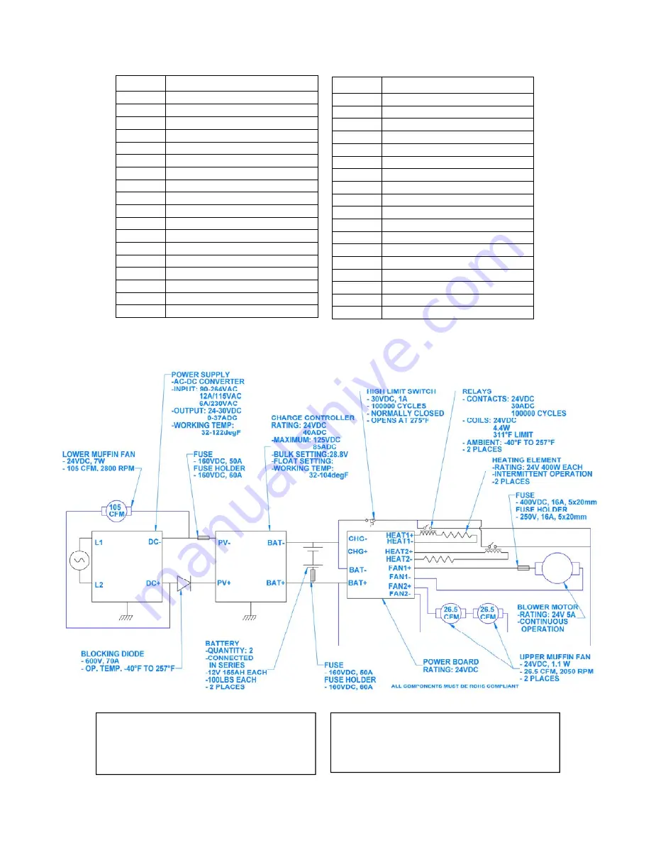
Page 13: ...WIRING SCHEMATIC 13...
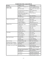
Page 14: ...y Replace both batteries Damaged wiring Repair wiring Damaged relay Replace relay Damaged controller Replace controller Damaged heating element Perform ohm reading Replace element Unit overheats Setpo...

Page 15: ...he equipment in accordance with the procedures described in the Operation Manual 6 Carter Hoffmann is NOT responsible for any loss of the customer s income loss of food product extra labor charges or...

Page 16: ...ter Hoffmann neither makes nor assumes and does not authorize any other person to make or assume any obligation or liability in connection with its products other than that covered in this warranty Th...

Reviews: