background image

20.

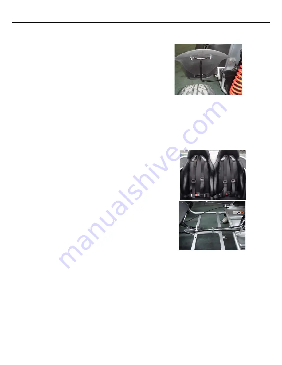
REAR FENDERS

a. Behind each seat is a mounting post for the rear

fenders.

b. Align the holes and slots of the fender bracket

with those of the mounting post.

c. Tighten with 10mm wrench.

21.

SEATS AND SEAT BELTS

a. Remove the seat hardware from the hardware box. This will be the silver bolts, nuts and

washers.

b. The seat belts are shipped bolted together. It is easier to install the seat belts with them

separated.

c. Start on the driver side by bolting the outer end of the seat belt to the seat belt mount

located behind the driver seat and in front of the rear fender.

d. With the driver seat turned upside down, slide the seat adjusters all the way back.
e. Put the seat in place by aligning the front brackets and rear holes.
f.

Insert a bolt in each hole from

top to bottom

leaving

the head of the bolt in the seat adjuster track.

g. You will have to hold the top of the bolt with a flat

head screw driver. Wedge the flat head screw driver
between the bolt head and the seat adjuster track and
tighten with a 12mm wrench.

h. Feed the seat belt through the holes in the top of the

seat.

i.

Bolt the top seat belt bracket to the seat belt mount
located directly behind the drivers head.

j.

Follow the same steps with the passenger seat. The
bolts for the passenger seat will be inserted from
bottom to top because the passenger seat does not
have an adjuster.

k. Tighten the passenger seat bolts with a 10mm

wrench.

l.

Tighten the seat belt bolts with a 14mm and 19mm
wrench.

50

SET-UP INSTRUCTIONS

INTERCEPTOR GTR 250

Summary of Contents for INTERCEPTOR GTR 250

Page 1: ...NUAL CAREFULLY IT CONTAINS IMPORTANT SAFETY INFORMATION This kart is designed for off road use only and does not comply with Federal Motor Vehicle Safety Standards Recommended for Ages 16 C GTR 2861 D...

Page 2: ......

Page 3: ...arefully read this Owner s Manual for the Interceptor GTR 250 as it contains important safety and maintenance information Failure to follow the warnings contained in this manual could result in seriou...

Page 4: ...Drive Is Y ourVehicle Ready T o Drive Safe Driving Precautions General Informations Specifications Locations Of Parts Operation Periodic ChecksAnd Services Service Instructions Service Information Wir...

Page 5: ...to impact 3 Spindles are bent due to impact 4 Paint is worn off of rear bumper indicating an extra rider 5 Axles are bent out of ordinary position either horizontally or vertically 6 Non factory alter...

Page 6: ...Any failure or damage to a part that does not influence its function will not be covered Normal wear of these parts is not covered Parts covered under the second year period would include but not nec...

Page 7: ...altered for use in racing or competition rented used under abnormal conditions or subject to abuse misuse neglect or improper maintenance Carter is not liable for any damage claim or liability claim p...

Page 8: ...per helmet eye protection and protective clothing _____7 Never operate the Vehicle on unsafe terrain or at excessive speeds _____8 Never do wheelies jumps or other stunts _____9 Never allow anyone to...

Page 9: ...ur own good judgment You will find important safety information in a variety of forms including Safety Labels _ On the kart Safety Messages _ Preceded by a safety alert symbol and one of two signal wo...

Page 10: ...ufactured for off road use only Its tires are not made for pavement and the kart does not have features required for use on public roads If you need to cross a paved or public road shut the kart s pow...

Page 11: ...riptions Do Not Operate this Kart at Night Lower visibility at night can greatly reduce a driver s judgment Driving at night is dangerous and will increase the possibility of an accident Never Run You...

Page 12: ...8...

Page 13: ...et eye protection boots gloves long pants and long sleeved shirt or jacket whenever you drive Although complete protection is not possible wearing proper gear can reduce the chance of injury when you...

Page 14: ...Age Recommendation It is strongly recommended that no one under the age of 16 be permitted to operate this go kart No Alcohol or Drugs Alcohol drugs and karts don t mix Even a small amount of alcohol...

Page 15: ...rain Tube Check for deposits in the drain tube If necessary clean the tube and check the air cleaner housing are corrected A pre drive inspection is a must not only for safety but because having a bre...

Page 16: ...oves smoothly without sticking and snaps back automatically when it is released Brakes Press the brake pedal several times check for proper brake pedal freeplay Make sure there is no brake fluid leaka...

Page 17: ...hey are not paved Drivers of street vehicles may have difficulty seeing and avoiding you which could lead to a collision In many states it is illegal to operate karts on public streets roads and highw...

Page 18: ...chances of losing control of the kart which can result in an accident Always drive at a speed that is proper for your kart the terrain visibility and other operating conditions and your experience Fai...

Page 19: ...UEL RECOMMENDATIONS FUEL Gasoline should be 92 octane or higher Unleaded gasoline is recommended BREAK IN PROCEDURE GENERAL INFORMATION MODEL IDENTIFICATION For the first 2 hours of riding do not exce...

Page 20: ...5 1 Carburetor 22mm Output Power 13 2kw 7000rpm Maximum Torque 20 6Nm 5500rpm Starting Electric Ignition C D I Lubrication Force Splash Transmission Automatic C V T system Spark Plug CR8E Plug Gap 0 8...

Page 21: ...14psi Rear Tire 25x10 12 14psi Front Suspension Dual A Arm Rear Suspension Dual A Arm Restraint System Dual 4 point Harness Final Drive Chain 520 x 66 WEIGHT Net Weight 345kgs 761lbs The specificatio...

Page 22: ...MIRROR SEAT BELT STEERING WHEEL R R WHEEL FR WHEEL DRIVE CHAIN TOW BALL REAR CARGO RACK HEADLIGHTS LOCATION OF PARTS 18...

Page 23: ...ENGINE STOP BUTTON LOCATION OF PARTS REAR CARGO RACK FUEL TANK ENGINE KEY SWITCH 12V OUTLET HEADLIGHT SWITCH HORN BLINKER RADIATOR 19...

Page 24: ...he key clockwise release the key when the engine starts Kart must be in neutral The engine will warm up within 5 minutes if the engine is cold you will need to pull the choke lever under the seat Warn...

Page 25: ...stop button test Repair as necessary h Check all nuts bolts and fasteners Check wheels to see that all axle nuts and lug nuts are tightened properly Check and tighten as necessary all other fasteners...

Page 26: ...nsure that NDUWengine is stopped Never operate this buggy when the provided seat is not securely fastened to do so could result in a strong possibility of severe personal injury or loss of life Before...

Page 27: ...hat is used to attatch itself to the frame b To adjust loosen one jam nut on one or both ends and adjust the appropriate direction c Tighten jam nuts SHIFT LEVER ADJUSTMENT a On the rear end of the ca...

Page 28: ...owly until you are familiar with it d The turning radius of this kart is small and agile so the centrifugal force is very high when turning at high speed Slow down to a more controllable speed when tu...

Page 29: ...ften if the kart is frequently operated at high speeds and after the kart has accumulated higher mileage Air Cleaner R C I Fuel Filter R I I Engine Oil Change R Tire Pressure I I Battery Inspection I...

Page 30: ...ngine oil and then squeeze it out Install the element on the element seat and then install the air cleaner cover Never use gasoline or acid organized solvent to clean the element CLAMP ELEMENT t l o B...

Page 31: ...ately 1200 cc or 1 1 4 quarts to top of filler neck with SAE 10W 30 oil e Check oil level before each use of kart or after each 10 hours of operation Add oil to bring up to proper level Do not mix var...

Page 32: ...the RPM reaches top speed e Adjust the screw and adjust the idle speed to an ideal value f Recheck and readjust the idle speed if necessary E Spark Plug a Remove the spark plug and inspect it each tim...

Page 33: ...plate bolts 2 front and 2 rear c Loosen air box bolts 4 total d Loosen muffler bolts 2 total e Slide engine forward and tighten all bolts NOTE When pushing the engine forward the front engine mount w...

Page 34: ...shock spring will increase as you scew to the right c Adjust accordingly to the weight of the riders I Front or Rear Shock Removal a You must first lift either the front or the rear of the kart off th...

Page 35: ...s It is only necessary to remove the four 4 lug nuts to remove the wheel Tighten the nuts after replacing the wheels K Rear Wheel Replacement Do not disassemble the castle nuts when you replace the re...

Page 36: ...n dimension B b To adjust the alignments loosen the lock nuts on both sides of Front Tie Rods To make Dimension B smaller turn the rod to the left Adjust the rod to the right direction to make Dimensi...

Page 37: ...eserve If the fuel level in the fuel tank becomes too low for the engine to operate with the fuel valve lever in the ON position turn the lever to the RES position to use the reserve fuel supply and r...

Page 38: ...nuts from steering block Grease inside of steer block periodically b Loosen steering shaft clamp nut and steering gear box c Remove steering shaft Nut Steering Shaft Link Steering Gear Box Clamp Nut...

Page 39: ...ver and steering gear box for wear c Check steering cover on sides of steering gear box and grease the ball head d Fill steering gear box with grease after cleaning the dust Replace the ball joint if...

Page 40: ...b Check the grease of ball joint Clean it if it is dirty and fill with grease c Replace the steering knuckle support if the ball joint is loose or steering isn t flexible Ball Head Dust Cover Filled W...

Page 41: ...bolt of upper and lower A arm front wheel c Check the nylon bushing of upper and lower A arm front wheel for wear Replace immediately if wear is present T Tie Rod a Tie rods should be checked for ease...

Page 42: ...tor by allowing engine to run out of fuel and use a fuel stabilizer b Lubricate engine cylinder by removing the air cleaner then spray engine fogging oil through the carburetor until motor dies c Do n...

Page 43: ...solvent and spin with your finger Never spin them vith compressed c Apply an ample amount of grease to the bearing and reinstall with bearing tool making sure it goes in straight Damage to the hub can...

Page 44: ...Motor Black White White Red Red Red White Green Red Black Booster Battery White Red Yellow Yellow Yellow Magnito Green Trigger Winding Green Turn Signal Light blue Velocity Generator Black Green Yell...

Page 45: ...uit then blow the hose with air Dry spark plug Wet spark plug Blowing is normal Blowing clogged No fuel in fuel tank Check if the pipes fuel tank to carburetor and intake vacuum are clogged Float valv...

Page 46: ...knock Knock Air cleaner clogged Poor fuel supply Lines in fuel tank evaporation system clogged Exhaust pipe clogged Fuel nozzle clogged in carburetor Malfunction of CDI Malfunction of AC alternator C...

Page 47: ...ack Spark plug fouled Malfunction of CDI Malfunction of AC generator Malfunction of ignition coil Open or short circuit in spark plug leads to malfunction of main switch Insufficient fuel in fuel tank...

Page 48: ...suddenly rear wheel rotates while engine is idling Poor initial driving poor climbing performance Drive belt worn out or deformed Weight roller worn out Movable drive face shaft worn out Driven pulley...

Page 49: ...ark plug Spark plug is incorrect heat range Excessive carbon deposited in combustion chamber Wrong type of fuel Fuel air mixture ratio is lean Use of poor quality fuel Worn piston and cylinder Fuel ai...

Page 50: ...have shock mount brackets The mounting brackets are located underneath the floorboard b Tighten bolts with 13mm and 14mm wrench 4 FRONT SHOCK a Place the bottom eye hole of the shock into the shock m...

Page 51: ...e back c Place the wheel assembly into position by aligning the holes in the wheel with the lugs on the front hubs d Tighten the lug nuts with a 15mm socket With the wheels off the ground you may not...

Page 52: ...14mm and 17mm wrench 14 REAR SHOCKS a Place the bottom eye hole of the shock into the shock mounts on the top a arms and insert bolt b Place the top eye hole of the shock into the shock mount located...

Page 53: ...end caps are in the hardware box Also remove 6 black anodized bolts and washers b Hold the top section of the rack about 1 off the rear frame and start the rear bolts Go ahead and tighten these rear...

Page 54: ...e Put the seat in place by aligning the front brackets and rear holes f Insert a bolt in each hole from top to bottom leaving the head of the bolt in the seat adjuster track g You will have to hold t...

Page 55: ...finger tighten f Place the top cross bar between the main bars with hoop pointing towards the front of the kart Align holes of the top cross bar with holes in the main bars g Insert a bolt and washer...

Page 56: ...ctric box cover from behind driver seat h Place battery into electric box i Place rectangular nuts under each pole of the battery j Bolt the green cable to the pole and the red cable to the pole k Sec...

Page 57: ...f the by pass valve When ONLY coolant comes out of the by pass valve and there are no air bubbles in the coolant reconnect the by pass hose d Continue to fill the radiator until the coolant level reac...

Page 58: ......

Page 59: ...Carter Brothers Manufacturing Co Inc 1871 U S Highway 231 South Brundidge Alabama 36010 Phone 800 523 5278 A Better Built Machine www carterbro com...

Page 60: ...2861 Differential This kart is designed for off road use only and does not comply with Federal Motor Vehicle Safety Standards Recommended for Ages 16 C GTR 2861 DIFFERENTIAL US 05 28 2007 Parts Manua...

Page 61: ......

Page 62: ...ven Pully Set A I C V Assembly Carburetor Assembly INDEX TO FRAME GROUP Frame Group Steering Shaft Assembly Suspension Arm Assembly Rear Cargo Rack Seat Belt Engine Muffler Air Cleaner Rear Swing Arm...

Page 63: ......

Page 64: ...2 REF QTY DESCRIPTION FIG 1 HEAD COVER PART NO 8240 3107 8213 3001 8213 3002 8213 3003 8200 3190 8100 0161 Head Cover Gasket Head Cover Head Cover Assy Reed Valve Comp Head Cover Bolt Flange Bolt SH 6...

Page 65: ...FIG 2 CYLINDER HEAD COMP...

Page 66: ...00 0291 8200 3509 8100 0212 8200 0163 8100 0161 8200 3115 8213 0012 8213 0019 Cylinder Head Comp Valve Stem Seal Cam Shaft In Valve Rocker Arm In Valve Rocker Arm Assy EX Valve Rocker Arm EX Valve Roc...

Page 67: ...021 8213 3022 8200 3191 8240 3108 8200 3606 8257 3013 8213 0035 8213 3023 8200 0167 8200 3301 8240 3106 Cylinder Comp Cylinder Assy Cylinder Gasket Cam Chain Tensioner Tensioner Lifter Assy Adjuster B...

Page 68: ...8213 3026 8213 3027 8213 3028 8213 3029 8240 3104 8200 3602 8200 3401 8200 0304 8100 0160 8200 3111 8222 3001 L Cover L Cover Plate L Cover Plate Gasket L Bearing Setting Plate L Cover Assy Bearing St...

Page 69: ...257 3014 8200 3404 8200 0193 8200 0591 8200 3507 8100 0160 8100 0162 8200 3112 8200 3114 8213 3035 L Crank Case Comp Setting Plate Mission Breather Tube Drain Tube Assy Tube Clip E5 Change SW Assy Cyl...

Page 70: ...213 3037 8213 3038 8213 3039 8200 3192 8200 0304 8200 3110 8100 0164 8100 0169 R Crank Case Comp Wave Washer E06 Crank Case Gasket Cam Chain Setting Plate Star Reduction Gear Comp Sta Reduction Gear S...

Page 71: ...FIG 7 R CASE COVER 26...

Page 72: ...213 0049 8200 3601 8200 0304 8200 0302 8100 0164 8100 0166 8100 0168 8200 3113 8222 0002 R Case Cover Comp Clamp E7 Tappet Adj Hole Cap Assy Oil Filter Screen Oil Filter Screw Spring Oil Level Gauge A...

Page 73: ...NO Fig 8 MOVABLE DRIVE FACE 8213 3047 8213 3048 8213 3049 8213 3050 8213 3051 8213 3052 8213 3053 8200 0551 8200 0214 Slide Piece Set Ramp Plate Weight Roller Set 6pes set Movable Drive Face Comp Driv...

Page 74: ...059 8213 3060 8213 3061 8213 3062 8213 3063 8213 0095 8222 3012 8200 3704 8222 3017 8222 3010 Crank Shaft Comp Piston Ring Set Piston Piston Pin Connecting Rod Conn Rod Assy Balance Shaft Drive Gear R...

Page 75: ...13 3067 8213 3068 8200 0214 8200 0551 8200 3701 8200 0403 8200 3403 8200 0304 8200 3804 8222 3015 8100 0175 R Cover Gasket Starting Clutch Gear Comp One Way Clutch Assy AC Gen Flywheel Set Flywheel Co...

Page 76: ...11 8213 3071 8213 3072 8257 3015 8200 3505 8200 3504 8200 3802 8222 3016 Balance Shaft Comp Balance Shaft Wave Washer 28 3x36x1 Balance Shaft Drive Gear A Balance Shaft Drive Gear B Balance Shaft Driv...

Page 77: ...FIG 12 MISSION CASE 45...

Page 78: ...9 8222 3020 8222 3018 Mission Case Inner Cover Stay A Mission Case Gasket Drive shaftt Counter Shaft Assy Counter Shaft Counter Gear A Counter Gear B Bush 20x13 Spacer Final Shaft Comp Final Shaft Fin...

Page 79: ...SCRIPTION FIG 13 OIL PUMP ASSEMBLY PART NO Fig 13 OIL PUMP ASSEMBLY 8213 3093 8223 3002 8231 3011 8200 3605 8200 3402 8200 0801 Oil Pump Assy Oil Pump Driven Sprocket Oil Pump Chain 48L Roller 2 5x11...

Page 80: ...R ASSEMBLY PARTS NO 8213 3094 8213 3095 8223 0001 8200 0590 8213 0029 8231 3012 8200 0196 8100 0162 Cyl Head Side Cover Assy Breather Tube Cam Sprocket Cam Sprocket Washer Centrifugal Disk Cam Chain 1...

Page 81: ...Fig 15 DRIVEN PULLEY SET 4 6 5 3 7 26...

Page 82: ...3109 8200 0214 8200 3293 8200 0551 8200 3803 8222 3013 8222 3021 8200 3706 8200 3604 8200 3901 Outer Clutch Comp Drive Plate Assy Drive Plate Comp Clutch Side Plate Clutch Spring Clutch Weight 3pes se...

Page 83: ...2 3 4 REF QTY DESCRIPTION FIG 16 A I C V ASSEMBLEY PART NO Fig 16 A I C V ASSEMBLEY 8213 3110 8213 3111 8213 3112 8213 0117 A I C V Unit A I C V Assy A I C V Inlet Pipe Joint Tube Assy A I A C Settin...

Page 84: ...BURETOR ASSEMBLY 8213 3113 8213 3114 8200 3603 8100 0206 8100 0164 8213 3115 8213 3116 8213 3117 8213 3118 8240 3001 Carb Assy Inlet Pipe Assy O Ring 34x2 0 Flange Nut 6mm Flange Bolt SH 6x22 Carb Nee...

Page 85: ...6 50 33 49 54 53 51 29 52 34 56 58 59 60 55 17 74 31 21 22 23 20 18 14 66 66 62 15 13 44 43 39 63 64 65 12 12 67 68 69 70 71 72 FIG 18 FRAME GROUP 7 6 6 30 7 6 6 30 7 6 7 6 7 6 7 6 7 6 6 30 4 40 41 28...

Page 86: ...quare C B C Top Bar FR Blue round C B C Top Bar FR Sliver round C B C Top Bar FR Carbon round C B C Bar L Blue square C B C Bar L Sliver square C B C Bar L Carbon square C B C Bar L Blue round C B C B...

Page 87: ...6 50 33 49 54 53 51 29 52 34 56 58 59 60 55 17 74 31 21 22 23 20 18 14 66 66 62 15 13 44 43 39 63 64 65 12 12 67 68 69 70 71 72 FIG 18 FRAME GROUP 7 6 6 30 7 6 6 30 7 6 7 6 7 6 7 6 7 6 6 30 4 40 41 28...

Page 88: ...Brake Hose Assy R Brake Hose Assy RR Reverse Cable Comp Throttle Cable Comp Parking Brake Cable Comp Manual Choke Cable Tube Seat 32 Headlight Bulb 35W 12V Flange Lock Nut M08 black Fr L Fender Brack...

Page 89: ...6 50 33 49 54 53 51 29 52 34 56 58 59 60 55 17 74 31 21 22 23 20 18 14 66 66 62 15 13 44 43 39 63 64 65 12 12 67 68 69 70 71 72 FIG 18 FRAME GROUP 7 6 6 30 7 6 6 30 7 6 7 6 7 6 7 6 7 6 6 30 4 40 41 28...

Page 90: ...re C B C Bar R Blue round C B C Bar R Sliver round C B C Bar R Carbon round R Light Front Cover R Light Center Cover R Light Rear Cover Lock Nut M05 Flange Lock Nut M08 250 ID Plate Trailered Plates T...

Page 91: ...15 16 17 7 26 35 37 36 30 29 32 31 24 34 28 27 19 18 20 21 22 23 10 4 1 6 33 40 42 39 43 44 41 40 38 3 32 23 2 8 5 9 10 13 25 12 36 44 29 36 40 14 15 16 19 18 20 21 22 23 38 38 16 16 FIG 19 STEERING...

Page 92: ...9 Steering Wheel Cover logo Bolt M06x12 K61 steering wheel Washer M06 Steering Wheel Steering Shaft Pan Screw M03X6 Brake Pedal Pad Needle Bearing 2617 Flange Bolt M08x30 Lock Washer M08 Steering Knuc...

Page 93: ...13 25 23 24 25 25 14 14 17 12 17 23 13 25 23 24 25 23 25 23 24 25 23 13 25 23 24 25 23 13 25 23 24 25 23 13 25 23 24 25 23 13 25 23 24 25 20 8 9 28 8 9 28 13 12 14 12 14 31 33 30 35 34 33 31 1 3 2 12...

Page 94: ...2 620 6011 600 6010 620 6010 616 0061 619 0061 600 5910 636 6005 Fr Wheel Hub Cap Cotter Pin 3x30 Castle Nut M14 Cap Lock Nut M10 L Fr Wheel Assy 23x7 10 Fr Hub R Strut Spindle Flange Bolt M08x16 Lock...

Page 95: ...K SEAT BELT 4 1 2 3 29 21 8 9 12 5 6 7 14 21 10 13 15 20 6 20 16 17 18 19 19 20 5 6 17 17 17 11 12 9 8 8 12 9 8 12 9 8 12 9 8 12 9 26 26 27 28 22 23 24 25 22 23 24 25 22 23 24 25 22 23 24 25 22 23 24...

Page 96: ...130 600 5113 600 5413 500 1045 600 0158 613 6011 640 6201 640 6001 500 1071 634 0004 2 Tail Light Bulb 21w 5w 12v Tail Light k61 500 short wire 38 Lock Nut M06 Rear Cargo Rack Blue Rear Cargo Rack Sli...

Page 97: ...32 25 6 30 22 33 23 24 20 18 21 19 10 9 12 8 14 7 15 16 17 11 13 10 1 4 3 34 16 9 10 3 2 31 31 31 20 7 8 37 38 36 39 2 40 41 42 20 18 21 19 20 20 18 21 19 20 20 18 21 19 20 43 43 44 44 43 43 44 44 35...

Page 98: ...04 640 6028 640 6029 640 6024 Engine Assy Screw ST M4 2x20 Flange Nut M6 Carburetor Assy Air Cleaner Assy Radiator Fan Flange Bolt M08x25 8000 Flange Lock Nut M08 8000 Flange Bolt M12x105 Flange Lock...

Page 99: ...4 38 4 38 38 38 9 7 5 6 6 20 18 6 18 19 17 10 17 18 19 20 6 20 18 19 17 19 20 18 17 6 18 19 20 17 18 19 20 6 18 17 18 18 18 18 18 19 18 18 19 5 4 38 38 2 2 2 2 2 2 2 2 2 2 21 19 20 17 18 2 2 2 2 29 1...

Page 100: ...2 637 6202 653 6002 500 1031 653 6024 Grease Fitting M06 O Ring D434 Rr R Fender Bracket k61 Cross Bolt M6x16 Flange Bolt M12x45 Flange Lock Nut M12 Washer Cap black Rr L Fender Bracket k61 Flange Bol...

Page 101: ...USING 12 13 14 15 16 17 18 19 21 22 14 15 16 17 18 13 45 45 7 24 27 27 24 25 25 25 25 28 29 30 31 27 27 1 2 3 4 39 6 8 9 10 11 26 23 33 35 41 26 32 10 9 8 37 5 34 35 38 33 36 36 40 40 42 42 40 40 43 4...

Page 102: ...8208 640 6032 Hex Nut M08 Lock Washer M08 Washer M08 Flange Bolt M08x80 R Bearing Holder Rr Housing Rr Brake Disk O ring Drive Chain Seal Brake Disk Bearing 941 25 Needle Bearing 6008 L Differential...

Page 103: ...1 2 6 4 3 21 8 9 7 23 24 17 5 10 11 18 15 18 19 25 16 13 14 22 20 12 18 15 10 18 26 4 27 28 29 31 FIG 25 WIRE HARNESS ELECTRICAL...

Page 104: ...609 6027 609 6028 609 6029 609 6030 640 6017 Front Wire Harness Rear Wire Harness Switch Panel Cover power supply L 609 6033 power supply R Pan Screw M05X12 Power Outlet Wire Harness zip Tie Ignition...

Page 105: ...2 5 6 8 9 10 10 10 10 10 10 10 10 10 10 10 11 12 10 FIG 26 Side Panels Hood Cover Fig 26 SIDE PANEL HOOD COVER Hook Front Left Trail Board Front Right Trail Board Front Middle Left Trail Board Front M...

Page 106: ...Open Ended Wrench 12x14 Open Ended Wrench 8x10 Slip Joint Pliers Spark Plug Wrench Tube Wrench ROD Screw Drive Handle Stem REF QTY DESCRIPTION PART NO Fig 27 TOOL KIT 608 0001 608 0002 608 0009 608 0...

Page 107: ...HAIR READ OWNER S MANUAL AND ALL LABELS BEFORE YOU OPERATE THIS GO KART NEVER OPERATE THIS GO KART WITHOUT PROPER INSTRUCTIONS Beginners require adult supervision NEVER OPERATE THIS GO KART ON PUBLIC...

Page 108: ...g Wheel Sticker Center Left Side Sticker Center Right Side Sticker Rear Decoration Sticker Rear Cargo Sticker 1 1 1 1 1 1 2 REF QTY DESCRIPTION PART NO 1 2 3 4 5 6 7 FIG 29 STICKERS Fig 29 STICKERS 60...

Page 109: ...Carter Brothers Manufacturing Co Inc 1871 U S Highway 231 South Brundidge Alabama 36010 Phone 800 523 5278...

Reviews: