3327 • P2 6/06
21
DC ELECTRICAL SYSTEM
SECTION 2
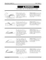
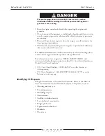
Never reset a breaker that has been automatically tripped without first
correcting the problem. Failure to follow this procedure may create a
dangerous situation.
NOTE:
Sometimes a circuit breaker location is labeled but no circuit breaker is
present. In this case, the component named on the label is an option that is not
installed on your boat.
DC Control Center
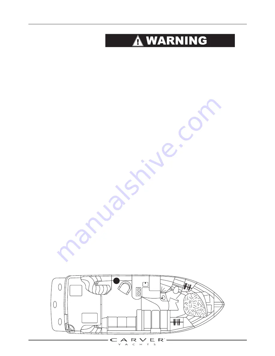
The DC Control Center, located in first cabinet on the port side of the salon
next to the entertainment center. It manages the power supply to most of the
boat’s 12-volt equipment, except for the equipment on the bridge.
To provide power to this breaker panel, turn the accessory battery master
disconnect switch to the “ON” position.
The DC Control Center contains the switches and circuit breakers
described below.
Bilge Blower
Use this switch to operate the bilge blowers. To activate this switch, first switch
the two Bilge Blower circuit breakers “ON.”
Bilge Blower (1 - 2)
These two breakers control the flow of electricity to the Bilge Blower switch at
the helm and on the DC Control Center. To supply power to these switches,
switch these breakers “ON.” Use the Bilge Blower switch to manually operate
the bilge blowers. The bilge blowers also operate automatically when the
starboard engine ignition switch is turned ON.
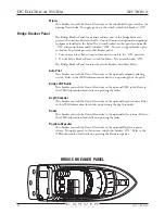
Bridge Accessory
This breaker controls the flow of electricity to any aftermarket accessories installed
at the bridge helm. Switch this breaker “ON” to activate these accessories. Refer to
the accessories’ manuals for information on operating the accessories.
DVD Player Aft
This breaker controls the flow of electricity to the optional salon DVD. To
supply power to the DVD, switch this breaker “ON.” Refer to the OEM
information for details on operating the DVD.
DC CONTROL CENTER
Summary of Contents for 380 SPORT
Page 1: ...HIN CDR _________________ 380 Sport Owner s Guide 2007 Version 1 ...
Page 2: ......
Page 4: ......
Page 6: ......
Page 8: ......
Page 28: ......
Page 40: ...28 3327 P2 6 06 DC ELECTRICAL SYSTEM SECTION 2 DC SCHEMATIC 3327 324 002 5 12 7 05 ...
Page 54: ...42 3327 P2 6 06 AC ELECTRICAL SYSTEMS SECTION 3 AC SCHEMATIC 3327 300 015 2 9 04 ...
Page 108: ......
Page 122: ......
Page 124: ...112 3327 P2 6 06 WARRANTY AND PARTS SECTION 9 Hatches ...
Page 129: ...3327 P2 6 06 117 WARRANTY AND PARTS SECTION 9 Bill of Material ...
Page 130: ......
Page 131: ...3327 P2 6 06 119 WARRANTY AND PARTS SECTION 9 Carver Limited Warranty ...

