3327 • P2 6/06
25
DC ELECTRICAL SYSTEM
SECTION 2
Safety Breaker Panel
The Safety Breaker Panel, located in a cabinet in the inboard end of the galley
counter on the standard and mid cabin models, manages the power supply to
various safety and other equipment.
Because of the importance of the safety equipment, the circuit breakers on this
panel should remain “ON” at all times. If a circuit breaker trips, immediately
identify and correct the cause of the problem, then reset the breaker.
Power is always provided to the Stereo Memory, High Water Alarm, SeaKey
®
,
Shower Sump, CO Detector and Auto Bilge Pump circuit breakers on this
panel. To provide power to the other circuit breakers, the accessory battery
master disconnect switch must be turned to the “ON” position. The Safety
Breaker Panel contains the switches and circuit breakers described below.
Accessory Main
This is the accessory battery master disconnect switch. Refer to Section 2 -
accessory Battery for a description of this master disconnect switch.
Auto Bilge Pump - 1, 2, 3
These breakers control the flow of electricity to the bilge pumps. Each pump
is activated automatically by a float switch whenever water within the bilge rises to a
predetermined level. These breakers must be “ON” whenever the boat is in the water.
NOTE:
Periodically test each bilge pump by lifting its float. The pump should turn
on when the float is lifted.
CO Detector
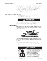
Carver has installed carbon monoxide (CO) detectors on your boat for your
safety. The CO detectors monitor the air throughout the boat’s cabin for the
presence of carbon monoxide. The CO Detector circuit breaker must be “ON”
for the CO detectors to operate.
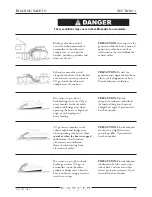
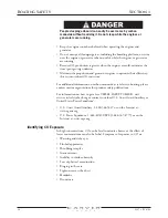
Always activate the CO detectors when the boat’s engines or generator
are running. Carbon monoxide is dangerous. Refer to Section 1 of this
Owner’s Guide for information on minimizing, detecting and controlling
carbon monoxide accumulation.
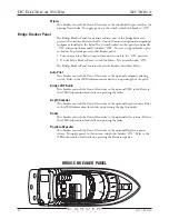
SAFETY BREAKER PANEL
Summary of Contents for 380 SPORT
Page 1: ...HIN CDR _________________ 380 Sport Owner s Guide 2007 Version 1 ...
Page 2: ......
Page 4: ......
Page 6: ......
Page 8: ......
Page 28: ......
Page 40: ...28 3327 P2 6 06 DC ELECTRICAL SYSTEM SECTION 2 DC SCHEMATIC 3327 324 002 5 12 7 05 ...
Page 54: ...42 3327 P2 6 06 AC ELECTRICAL SYSTEMS SECTION 3 AC SCHEMATIC 3327 300 015 2 9 04 ...
Page 108: ......
Page 122: ......
Page 124: ...112 3327 P2 6 06 WARRANTY AND PARTS SECTION 9 Hatches ...
Page 129: ...3327 P2 6 06 117 WARRANTY AND PARTS SECTION 9 Bill of Material ...
Page 130: ......
Page 131: ...3327 P2 6 06 119 WARRANTY AND PARTS SECTION 9 Carver Limited Warranty ...


