26
3327 • P2 6/06
DC ELECTRICAL SYSTEM
SECTION 2
When the CO detectors are operating, they alert you to the presence of carbon
monoxide in the cabin by emitting a loud, high pitched sound. When you hear
this alarm, determine the cause and correct it immediately.
There is a test button on each CO detector. Test each unit on a weekly basis.
If you suspect that a CO detector is faulty, have your dealer repair or replace it
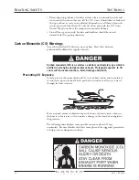
immediately. Refer to Section 1 - Carbon Monoxide (CO) Warnings for more
information on CO.
High Water
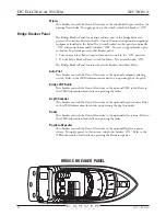
This breaker controls the flow of electricity to the high bilge water alarm. Refer
to Section 4 - Bilge System for a description of the high bilge water alarm. This
breaker must be “ON” whenever the boat is in the water.
Main - One
This breaker protects the circuitry between the DC Control Center and the
accessory battery. This breaker must be “ON” to provide power to the DC
Control Center.
Main - Two
This breaker helps protect the circuitry between the Bridge Breaker Panel and
the accessory battery. This breaker must be “ON” to provide power to the
Bridge Breaker Panel.
SeaKey
®
This breaker controls the flow of electricity to the Volvo SeaKey
telemetric
equipment. This equipment is installed on all Carver yachts, but can only be
activated with a current service subscription. If you have a subscription, then
this breaker must be “ON” to provide electricity to the equipment. Refer to the
OEM information for details on the SeaKey equipment.
Shower Sump
This breaker controls the flow of electricity to the sump pump. Because the
sump is located below the boat’s water line, the sump pump is needed to pump
used (grey) water from the head sink and shower, as well as air conditioning
condensation overboard. The sump pump is activated automatically by a float
switch whenever water within the sump rises above a predetermined level. Make
sure the Shower Sump circuit breaker is “ON” before using the shower, head
sink or air conditioning.
Stereo Memory
This breaker controls the flow of electricity to the salon stereo system. This
breaker should always be “ON” to maintain the information programmed
into the stereo’s memory. If this breaker is ever switched “OFF,” you will
have to reprogram the stereo. Refer to the OEM information for details on
programming the stereo.
Windlass
This breaker controls the flow of electricity to the controls that operate the
windlass. A set of windlass controls are located both at the helm and on the fore
deck. To supply power to the controls, switch this breaker “ON.” Refer to the
OEM information for details on operating the windlass.
NOTE:
The windlass circuit also contains an in-line fuse that protects the windlass
switch solenoid. This fuse is located in the anchor chain locker.
Summary of Contents for 380 SPORT
Page 1: ...HIN CDR _________________ 380 Sport Owner s Guide 2007 Version 1 ...
Page 2: ......
Page 4: ......
Page 6: ......
Page 8: ......
Page 28: ......
Page 40: ...28 3327 P2 6 06 DC ELECTRICAL SYSTEM SECTION 2 DC SCHEMATIC 3327 324 002 5 12 7 05 ...
Page 54: ...42 3327 P2 6 06 AC ELECTRICAL SYSTEMS SECTION 3 AC SCHEMATIC 3327 300 015 2 9 04 ...
Page 108: ......
Page 122: ......
Page 124: ...112 3327 P2 6 06 WARRANTY AND PARTS SECTION 9 Hatches ...
Page 129: ...3327 P2 6 06 117 WARRANTY AND PARTS SECTION 9 Bill of Material ...
Page 130: ......
Page 131: ...3327 P2 6 06 119 WARRANTY AND PARTS SECTION 9 Carver Limited Warranty ...

