54
3327 • P2 6/06
INTERNAL SYSTEMS
SECTION 4
Manual Operation
To operate the bilge pumps manually, press the Forward, Mid, and Aft Bilge Pump
switches, located at the helm, to their up position. This activates the two bilge pumps.
When operating a bilge pump in manual mode, turn the pump “OFF” when
the bilge water level is so low that the pump can not drain it. Allowing the
pump to operate when it is not pumping water can damage it.
Hull Drain
Your boat is equipped with one hull drain. The drain allows water to drain
from the bilges while the boat is in dry storage. The boat and cradle should be
positioned to allow water to flow toward the hull drain. The drain is located in
the transom in the deepest portion of the hull’s “V.”
Make sure the hull drain plug is securely screwed into the hull drain
before launching the boat.
Sanitation System
Your boat’s sanitation system includes the head, waste tank, and the optional
overboard waste discharge system. When properly used, this system conforms to
all United States antipollution laws.
Toilet
The toilet uses either seawater (standard) or fresh water (optional) and an electric
pump to remove waste from the head. If you have guests who are unfamiliar
with marine sanitation systems, instruct them on how to properly use the toilet.
Refer to the OEM information for details on operating the toilet.
To operate the toilet system:
1. Provide water to the toilet:
For a seawater toilet, open the seacock that supplies seawater to the toilet.
The seacock is located in the engine room forward of the port engine. Refer
to Section 9 - Engine Room for the exact location of the seacock.
For a fresh water toilet, either make sure there is sufficient water in the fresh
water tank or connect the fresh water system to shore water.
2. On the Safety Breaker Panel:
a.
Turn the accessory battery master disconnect switch to the “ON”
position.
b. Switch the Main - One circuit breaker “ON.”
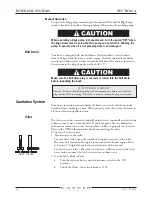
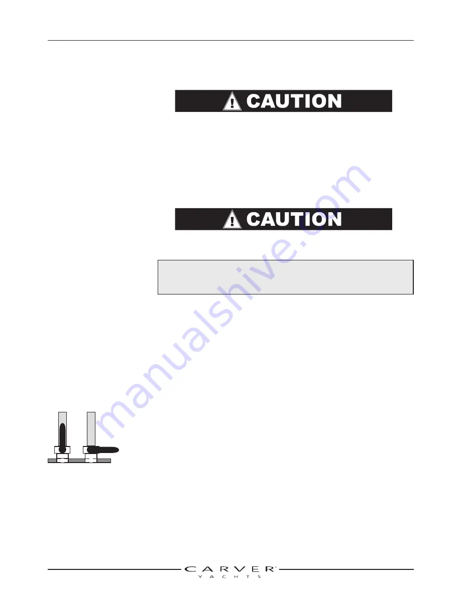
Open Closed
A TIP FROM CARVER!
Coat the threads of the hull drain plug with waterproof grease before you install the
plug into the hull drain fitting. This makes it easier to remove the plug at a later date.
Summary of Contents for 380 SPORT
Page 1: ...HIN CDR _________________ 380 Sport Owner s Guide 2007 Version 1 ...
Page 2: ......
Page 4: ......
Page 6: ......
Page 8: ......
Page 28: ......
Page 40: ...28 3327 P2 6 06 DC ELECTRICAL SYSTEM SECTION 2 DC SCHEMATIC 3327 324 002 5 12 7 05 ...
Page 54: ...42 3327 P2 6 06 AC ELECTRICAL SYSTEMS SECTION 3 AC SCHEMATIC 3327 300 015 2 9 04 ...
Page 108: ......
Page 122: ......
Page 124: ...112 3327 P2 6 06 WARRANTY AND PARTS SECTION 9 Hatches ...
Page 129: ...3327 P2 6 06 117 WARRANTY AND PARTS SECTION 9 Bill of Material ...
Page 130: ......
Page 131: ...3327 P2 6 06 119 WARRANTY AND PARTS SECTION 9 Carver Limited Warranty ...


