3327 • P2 6/06
71
PROPULSION
SECTION 5
11. Monitor the fuel tank’s air vent. When the fuel tank is almost full, air whistles
through the vent.
12. Replace the fuel fill deck plate.
13. Repeat steps 9 - 12 for the remaining fuel tank.
14. Wipe up all spilled fuel.
Pre-Start Checklist
1. Read and understand this Owner’s Guide and all OEM information.
2. Check both fuel gauges to verify that you have sufficient fuel for your trip.
3. Inspect the engine room:
a.
Sniff for fuel vapor.
b. Check the bilge water level.
c.
Check for oil in the bilge.
d. Check the crank case oil level in each engine.
e.
Make an overall inspection of the engine room to look for signs
of potential problems.
f.
Follow all maintenance instructions described in Section 7.
4. Turn both engine battery and the accessory battery master disconnect
switches to the “ON” position.
5. On the Safety Breaker Panel:
a.
Verify that both Auto Bilge Pump circuit breakers are “ON.”
b. Switch the Main - One circuit breaker “ON.”
c.
Switch “ON” any other circuit breakers for equipment you may need.
6. On the DC Control Center:
a.
Switch the Main circuit breaker “ON.”
b. Switch the two Bilge Blower circuit breakers “ON.”
c.
Switch “ON” any other circuit breakers for equipment you may need.
7. Turn the bilge blowers “ON” using the blower switch at the helm or on the
DC Control Center.
Make sure the bilge blowers are operating properly by feeling for air being
blown from the bilge vents. These vents are located on either side of the
cabin’s exterior just aft of the salon windows.
Operate the blowers for at least 4 minutes and until the engine room is free
of any fuel vapor before starting the engines.
8. Verify that all safety gear is onboard and in proper operating condition. Make
sure your boat carries all safety equipment required by federal, state and local
regulations.
9. Verify that you have an adequate supply of fresh water.
10. Check the level of waste in the waste tank. Empty them if necessary. Refer to
Section 4 - Emptying the Waste Tank.
11. Disconnect and store the shore power cord(s) and shore water hose.
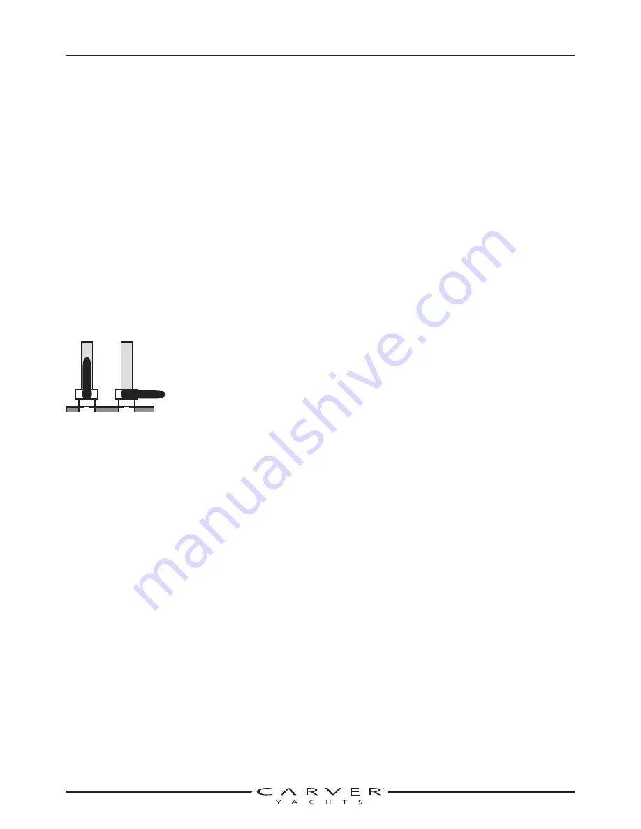
Open Closed
Summary of Contents for 380 SPORT
Page 1: ...HIN CDR _________________ 380 Sport Owner s Guide 2007 Version 1 ...
Page 2: ......
Page 4: ......
Page 6: ......
Page 8: ......
Page 28: ......
Page 40: ...28 3327 P2 6 06 DC ELECTRICAL SYSTEM SECTION 2 DC SCHEMATIC 3327 324 002 5 12 7 05 ...
Page 54: ...42 3327 P2 6 06 AC ELECTRICAL SYSTEMS SECTION 3 AC SCHEMATIC 3327 300 015 2 9 04 ...
Page 108: ......
Page 122: ......
Page 124: ...112 3327 P2 6 06 WARRANTY AND PARTS SECTION 9 Hatches ...
Page 129: ...3327 P2 6 06 117 WARRANTY AND PARTS SECTION 9 Bill of Material ...
Page 130: ......
Page 131: ...3327 P2 6 06 119 WARRANTY AND PARTS SECTION 9 Carver Limited Warranty ...


