S
ECTION
3
AC E
LECTRICAL
S
YSTEM
75
4527 5/04
Fault Circuit Interrupters" later in this section for
more information.
Receptacles Guest Stateroom
This breaker controls the flow of electricity to the recep-
tacles in the forward stateroom. Switch this breaker
"ON" to supply power to these receptacles. Use the
receptacles as you would the outlets in your home.
NOTE: The GFCI receptacle for this group of receptacles
is located in the guest stateroom head next to the sink. If
the appropriate circuit breakers are "ON" but power is
still not available at any of the receptacles in this group,
one or both of the GFCI breakers may have tripped.
Refer to "Ground Fault Circuit Interrupters" later in
this section for more information.
Receptacles Exterior
This breaker controls the flow of electricity to the recep-
tacles in the cockpit and on the flybridge. Switch this
breaker "ON" to supply power to these receptacles. Use
the receptacles as you would the outlets in your home.
NOTE: The GFCI receptacle for this group of receptacles
is located on the transom to the left of the salon’s sliding
door. If the appropriate circuit breakers are "ON" but
power is still not available at any of the receptacles in
this group, one or both of the GFCI breakers may have
tripped. Refer to "Ground Fault Circuit Interrupt-
ers" later in this section for more information.
Water Heater
Do not supply power to the water heater when it is
empty. Doing so may damage the unit’s heating ele-
ment and cause a fire. Refer to the "Fresh Water
System" portion of Section 4 to fill, pressurize and
prime the fresh water system before turning on the
water heater.
This breaker controls the flow of electricity to the water
heater. The water heater supplies hot water to your
fresh water system. Switch this breaker "ON" to supply
power to the water heater. The water heater is located
under a hatch in the engine room between the propul-
A T
IP
F
ROM
C
ARVER
!
Whenever your water heater has
been winterized for storage, or
your water tanks are empty,
Carver recommends taping the
Water Heater breaker in the
"OFF" position. This helps
prevent the breaker from acci-
dentally being switched "ON"
when no water is in the water
system.
Summary of Contents for 45 Voyager 2005
Page 1: ...45 Voyager Owner s Guide HIN CDR 2005 Version 1 ...
Page 2: ......
Page 4: ......
Page 8: ...PREFACE 5 01 ...
Page 32: ...22 BOATING SAFETY 4527 6 02 SECTION 1 NOTES ...
Page 33: ...23 4527 6 02 SECTION 1 BOATING SAFETY NOTES ...
Page 34: ...24 BOATING SAFETY 4527 6 02 SECTION 1 NOTES ...
Page 44: ...DC ELECTRICAL SYSTEM SECTION 2 34 4527 5 04 MAIN DC SUBPANEL ...
Page 65: ...SECTION 2 DC ELECTRICAL SYSTEM 55 4527 5 04 Revised 12 19 97 DC ELECTRICAL SYSTEM CONTINUED ...
Page 66: ...DC ELECTRICAL SYSTEM SECTION 2 56 4527 5 04 NOTES ...
Page 67: ...SECTION 2 DC ELECTRICAL SYSTEM 57 4527 5 04 NOTES ...
Page 68: ...DC ELECTRICAL SYSTEM SECTION 2 58 4527 5 04 NOTES ...
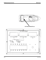
Page 80: ...AC ELECTRICAL SYSTEM SECTION 3 70 4527 5 04 AC SYSTEM MAINS PANEL ...
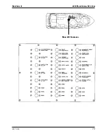
Page 83: ...SECTION 3 AC ELECTRICAL SYSTEM 73 4527 5 04 MAIN AC SUBPANEL ...
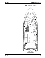
Page 91: ...SECTION 3 AC ELECTRICAL SYSTEM 81 4527 5 04 GFCI RECEPTACLE LOCATIONS ...
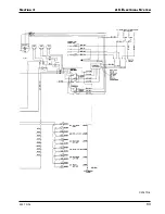
Page 95: ...SECTION 3 AC ELECTRICAL SYSTEM 85 4527 5 04 ...
Page 98: ...AC ELECTRICAL SYSTEM SECTION 3 88 4527 5 04 AC Wiring Schematic 110 Volt 60 Hz C2057D 1 ...
Page 99: ...SECTION 3 AC ELECTRICAL SYSTEM 89 4527 5 04 C2057D 2 ...
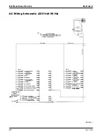
Page 100: ...AC ELECTRICAL SYSTEM SECTION 3 90 4527 5 04 AC Wiring Schematic 220 Volt 50 Hz C2058D 1 ...
Page 101: ...SECTION 3 AC ELECTRICAL SYSTEM 91 4527 5 04 C2058D 2 ...
Page 102: ...AC ELECTRICAL SYSTEM SECTION 3 92 4527 5 04 NOTES ...
Page 119: ...SECTION 4 INTERNAL SYSTEMS 109 4527 10 99 SANITATION SYSTEM C2030D B ...
Page 124: ...INTERNAL SYSTEMS SECTION 4 114 4527 10 99 GREY WATER SYSTEM ...
Page 129: ...SECTION 4 INTERNAL SYSTEMS 119 4527 10 99 NOTES ...
Page 130: ...INTERNAL SYSTEMS SECTION 4 120 4527 10 99 NOTES ...
Page 146: ...PROPULSION SECTION 5 136 4527 3 99 NOTES ...
Page 147: ...SECTION 5 PROPULSION 137 4527 3 99 NOTES ...
Page 148: ...PROPULSION SECTION 5 138 4527 3 99 NOTES ...
Page 163: ...SECTION 6 OPERATING AND MANEUVERING 153 4527 3 99 NOTES ...
Page 164: ...OPERATING AND MANEUVERING SECTION 6 154 4527 3 99 NOTES ...
Page 175: ...SECTION 7 MAINTENANCE 165 4527 8 04 ...
Page 178: ...MAINTENANCE SECTION 7 168 4527 8 04 ...
Page 185: ...SECTION 7 MAINTENANCE 175 4527 8 04 NOTES ...
Page 186: ...MAINTENANCE SECTION 7 176 4527 8 04 NOTES ...
Page 191: ...SECTION 8 WINTERIZATION AND STORAGE 181 4527 10 99 FRESH WATER SYSTEM ...
Page 196: ...WINTERIZATION AND STORAGE SECTION 8 186 4527 10 99 SANITATION SYSTEM ...
Page 205: ...SECTION 8 WINTERIZATION AND STORAGE 195 4527 10 99 IMPORTANT ANTIFREEZE BULLETIN ...
Page 206: ...WINTERIZATION AND STORAGE SECTION 8 196 4527 10 99 ...
Page 209: ...SECTION 8 WINTERIZATION AND STORAGE 199 4527 10 99 NOTES ...
Page 210: ...WINTERIZATION AND STORAGE SECTION 8 200 4527 10 99 NOTES ...
Page 216: ...WARRANTY AND PARTS SECTION 9 206 4527 5 04 Serial Number Record Sheet ...
Page 227: ...SECTION 9 WARRANTY AND PARTS 217 4527 5 04 Carver Limited Warranty ...
Page 228: ...WARRANTY AND PARTS SECTION 9 218 4527 5 04 ...
Page 231: ...INDEX 4527 3 99 Windshield washer 44 Windshield wipers 43 44 Z Zinc anodes 84 193 ...
Page 232: ...INDEX 4527 3 99 ...


