through your headphones. (see 24.)
10. EFFECTS 1 & 2
This control adjusts the level a signal being sent from each
channel, one to the internal digital effects processor (
EFFECTS
1
), and one to the
EFFECTS 2
output jack via the
EFFECTS
2
master send control to drive an outboard processor. The
internal
EFFECTS 1
are ready to use and do not require addi-
tional cable connections to achieve their full stereo imaging.
11. EFFECTS 3
A third send routes a signal from each chan-
nel’s
EFFECTS 3
control to the
EFFECTS 3
master send control.
12. STEREO PANNING
Each channel’s
PAN
control allows sweeping stereo effects
when panning from L to R for recordings or live sound.
Superior channel separation is available over other mixers
because of the “dual element” pan controls providing 15dB
greater separation.
13. CHANNEL SIGNAL GREEN LED
The signal indicator is pre-fader and post EQ. This LED ver-
ifies that the channel is receiving a signal from the mic or
instrument inputs.
14. CHANNEL PEAK RED LED
This peak indicator is pre-fader and post EQ. A constantly
lit LED indicates the signal is probably needs a reduction in
GAIN to prevent input overloading.
15. CHANNEL MUTE SWITCH
Mutes a channel instantly without touching your faders. This
is extremely useful when you need to mute channels. You
won’t lose the settings on your faders.
16. CHANNEL PFL SWITCH
This switch allows the operator to monitor a channel in the
headphone mix to set tone and gain levels.
17. AUDIO TAPER FADERS
Slide all faders down when connecting your inputs. Increase
each channels fader to achieve the overall mix. Calibrated 60mm
faders with audio taper are featured for smooth fade-outs.
MASTER SECTION
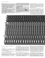
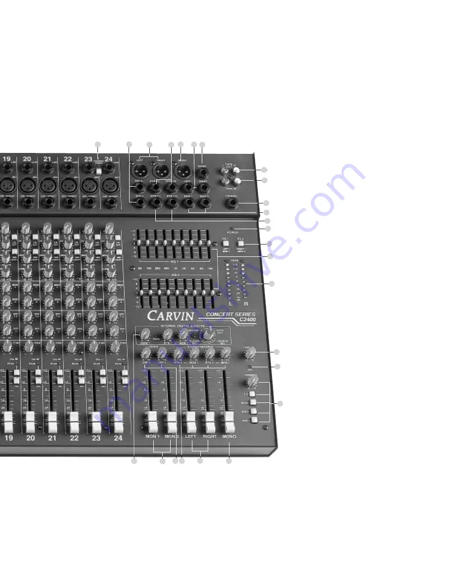
18. INTERNAL STEREO DIGITAL EFFECTS
The
MASTER EFFECTS SEND 1
control takes the effects send
from the channels and sends it to the internal digital effects
system. The
EFFECTS PEAK LED
helps to set the proper
level and prevents overloading the internal digital effects
system.
RETURN 1
sets the effects level going to the
LEFT/RIGHT mix
MONITOR 1
is an exclusive feature allowing
you to send the internal digital effects to your MONITOR 1 speak-
ers. Select from sixteen premium effects: four REVERBS—two
rooms, plate & stadium, six ECHOES/REVERBS—50ms to
500ms, four sweeping CHORUS/REVERBS and two FLANG-
ING/REVERBS—all in true STEREO!
19. MASTER MONITOR 1 & 2 FADERS
Large 60mm faders control the master output level of the
monitors. Since the MONITORS are not affected by the chan-
nel’s tone controls (pre-channel EQ and pre-channel insert)
you are free to EQ your monitor signals externally to con-
trol stage feedback. You may use an external equalizer
(Carvin’s EQ2015 or EQ2030), a monitor amp with an
onboard EQ (HT760M) or use the EQ 1 & 2 switch (see 29.)
20. EFFECTS SEND 2 & 3
Two more sends for outboard effects processors. Each send
feeds their respective effects output jack (EFF 2 AND EFF 3).
21. MASTER RETURN EFFECTS 2 & 3
Return up to 4 mono or 2 stereo effects from 2 stereo con-
trols. You can also send effects to your MON 1 speakers.
22. MASTER LEFT & RIGHT FADERS
These faders send the main stereo mix created by all channel
faders to the main balanced and unbalanced output connectors.
The left and right signals will be identical if you do not pan your
individual channels left or right to create a stereo image.
23. MASTER MONO FADER
The C series creates an extra mono signal from the R & L
master faders to be used for a mono house PA or subwoofer.
24. HEADPHONE AND METER SOURCE
The
PHONES
control sets the desired level of the
PHONES
jack. The
PFL
,
L/R
,
MONO
and
MONITOR 1 & 2
switches allow
for isolation of these events through the headphones.
25. PFL RED LED
Indicates that the headphone & meters are monitoring the
channels where the
PFL
is switched on.
26. TAPE IN RETURN LEVEL
Controls the return levels of the L & R tape (CD) into the mixer
27. R/L LED VU METERS
This group of LEDs are ten segment 6 dB resolution meters that
give the operator a visual of the mixer output.
28. DUAL PRECISION 9 BAND GRAPHIC EQs
are octave filters at 60,125, 250, 500, 1k, 2k, 4k, 8k & 16k
Hz centers that offer precise adjustment to help eliminate
feedback & enhance tone of the main or monitor mix.
29. EQ SWITCH 1 & 2
These switches swap the EQ’s from the standard LEFT, RIGHT
main outputs (OUT) to the MON 1 & MON 2 outputs (IN) respec-
tively. This allows the equalizers to be used with monitor amps
and eliminates the need for outboard monitor equalizers.
30. POWER LED
Verifies the mixer is on.
31. RETURN 2 L/R CONNECTORS
Returns a stereo signal from an external effects processor.
Connect the output of an external effect to these points.
32. RETURN 3 L/R CONNECTORS
Returns a stereo signal from an external effect. Connect your
effects processors’ stereo outputs to these stereo returns.
33. EFFECTS 2 & 3 CONNECTORS
1/4” output connectors drive external effects. Connect your
effects processor’s inputs to these outputs.
34. MONITOR 1 & 2 CONNECTORS
The Concert Series provides balanced 1/4” outputs for long cable
runs. Connect your monitor power amp(s) to these outputs.
35. HEADPHONE JACK
1/4” stereo jack for headphone or control room output.
36. RCA R & L TAPE OUT
Stereo RCA jacks for connecting a tape recorder.
37. RCA R & L TAPE IN
For stereo playback of a tape/CD or use as a 4th stereo return.
38.–39. LEFT /
RIGHT XLR & 1/4” CONNECTORS
This set of balanced and unbalanced connectors are for
connect main mix to external power amp(s).
4 0.–41. MONO XLR & 1/4” CONNECTORS
A set of balanced and unbalanced mono outputs for PA or
Subwoofer (requires subwoofer crossover & power amp).
42. MIC PHANTOM POWER SWITCH / RED LED
This switch provides phantom power for condenser mics in
groups of 8 channels. This allows other channel groups to
remain non-powered to use the LINE inputs for instruments
and MIC inputs for mics that don’t require phantom power.
18
25
26
27
28
29
30
32
34
35
37
36
41
39
40
31
38
33
42
23
19
21
24
22
20


