background image

USER GUIDE 

FOR WALL MOUNTED FAN COIL UNIT 

Summary of Contents for CZHW-40

Page 1: ...USER GUIDE FOR WALL MOUNTED FAN COIL UNIT...

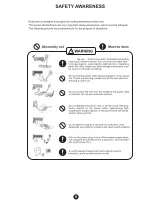
Page 2: ...OTE 3 OPERATIONAL INSTRUCTIONS 4 WORK LIMITS 2 SAFETY AWARENESS 6 INDEX TROUBLE SHOOTING 8 GENERAL DIMENSIONS 10 TECHNICAL DATA 10 INSTALLATION INSTRUCTIONS 11 INSTALLATION INSTRUCTIONS 12 INSTALLATIO...

Page 3: ...r cannot be held liable for any damage or injury caused by misuse of the appliance or by partial or superf cial knowledge of the information contained in this guide Installations must be performed by...

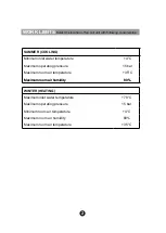
Page 4: ...Maximum room air humidity 80 WINTER HEATING Maximum inlet water temperature 70 C Maximum operating pressure 15 bar Minimum room air temperature 4 C Maximum room air humidity 80 Maximum room air temper...

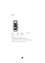
Page 5: ...perating range for the remote handset is 6 meters 2 The unit will beep once it receives signal from the remote control 3 User has to refer the photo of same remote mentioned above what he has get with...

Page 6: ...SPEED Pressing the Fan Speed key will change fan speed with the sequence below Low Med High Auto Auto Speed is only activated in AC Mode While increasing room temperature 0 a Low fan change to medium...

Page 7: ...e between Hour Minute setting and press the SET button Note This feature will work only when the unit is On TURBO Turbo function is selectable in Cool Heat mode only This function bypass The delay tim...

Page 8: ...The unit 6...

Page 9: ...Indoor unit 7...

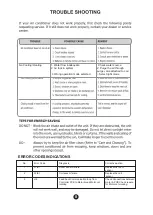
Page 10: ...selected 3 Select right mode No 1 Error Code F1 E1 Diagnosis Room sensor failure Corrective action Replace the room sensor 2 F2 E1 Coil sensor failure Replace the coil sensor 5 H6 Feed back Communica...

Page 11: ...9...

Page 12: ...40 CZHW 60 CZHW3V 60 CZHW 80 CZHW3V 80 Drain Connection OD 5 8 5 8 5 8 Inlet Pipe Connection 1 2 5 8 5 8 Outlet Pipe Connection 1 2 5 8 5 8 Length L 1070 1131 1080 Depth D 240 214 245 Hight H 300 361...

Page 13: ...f gure below mark the location for the wall plugs and the hole for the pipings PLAN DIMENSIONS FOR MOUNTING PLATE INSTALLATION OUTLINE UNIT MOUNTING PLATE LEFT BACKWARD PIPING HOLE RIGHT BACKWARD PIPI...

Page 14: ...4 Take out drain hose from hole provide in Wall...

Page 15: ...12 5 Connect the Inlet Outlet pipes with specified torque FLARING Ensure flaring as per below...

Page 16: ...INDOOR UNIT WIRING PANEL L N EXTERNAL ACTUATOR VALVE POWER SUPPLY 230V 50Hz L N C N INDOOR UNIT WIRING PANEL L N INTERNAL ACTUATOR VALVE POWER SUPPLY 230V 50Hz For indoor unit models with internal ac...

Page 17: ...14...

Reviews: