- 7 -
CALIBRATION MODE
Moving method
Open the top cover of indicator and power on with pressing CAL switch in the left
top. At that time, LCD screen shows “ZEro=tESt tArE=CAL” message and pressing
‘TARE’ key moves to CAL 1.
Calibration menu (CAL 1 ~ CAL 5)
CAL 1 : Maximum Capacity Set
CAL 2 : Minimum Division Set
CAL 3 : Setting Weight in Span Calibration
CAL 4 : Zero Calibration
CAL 5 : Span Calibration
Digit input method
NET/GROSS Key : Increase the first place value by 1.
TARE Key : Move to the left by 1 place.
ZERO/MODE Key : Set the inputted value to “0”.
ENTER Key : Move to the next menu.
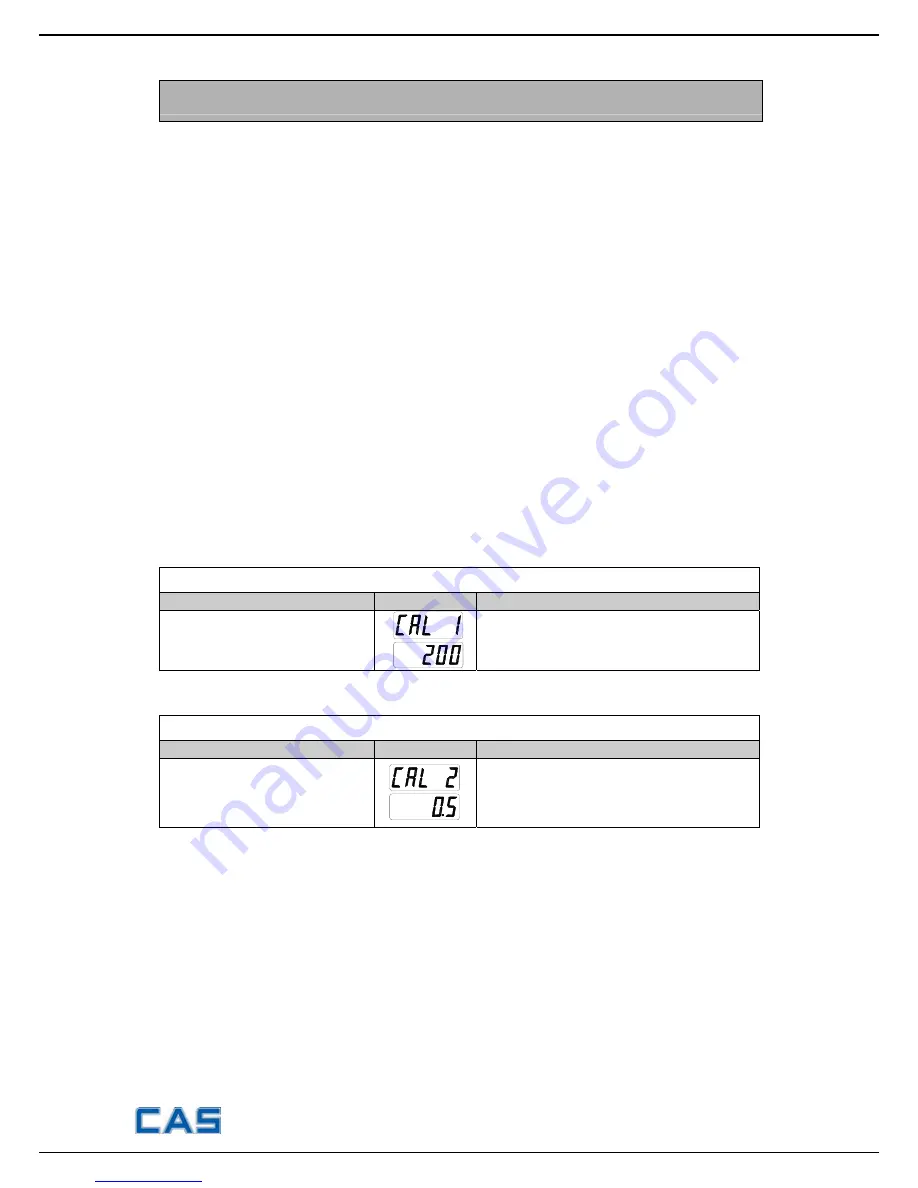
CAL 1
FUNCTION : Maximum Capacity Set (Range : 1 ~ 99,999)
KEY
LC DISPLAY
DESCRIPTION
Input by digit input method.
ENTER : save and go to next menu
CAL 1 condition
200 Kg
CAL 2
FUNCTION : Minimum Division Set (Range : 0.001 ~ 50)
KEY
LC DISPLAY
DESCRIPTION
NET/GROSS key:
Input the next division
TARE key:
Input the previous division
ENTER key: Move to the next menu
CAL 2 condition
0.5 Kg
▶
Note 1. The minimum division means the value of one division.
▶
Note 2. External resolution is obtained by dividing the min. division by the
maximum capacity. Set the resolution to be within 1/10,000.
▶
Note 3. The maximum capacity/minimum division is over 10,000, error message
“CH 11” will occur.
Downloaded from
www.Manualslib.com
manuals search engine
Summary of Contents for BW-15
Page 10: ... 10 SCHEMATIC DIAGRAM Downloaded from www Manualslib com manuals search engine ...
Page 12: ... 12 DISPLAY PCB BOTTOM SIDE TOP SIDE Downloaded from www Manualslib com manuals search engine ...
Page 13: ... 13 CONNECTION DIAGRAM Downloaded from www Manualslib com manuals search engine ...
Page 21: ... 21 SET C T BOX ASS Y LOW CAPACITY Downloaded from www Manualslib com manuals search engine ...
Page 22: ... 22 BODY ASS Y HIGH CAPACITY Downloaded from www Manualslib com manuals search engine ...


