background image

Reference Manual V1.10 


Software Versions 3.xx 

X300-621-110


Page 1 

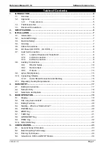
Table of Contents 

1.


INTRODUCTION ................................................................................................................... 4


1.1.


Overview .................................................................................................................... 4


1.2.


Approvals ................................................................................................................... 4


1.2.1.


Trade versions ............................................................................................ 5


1.3.


The Manuals Set ........................................................................................................ 5


1.4.


Document Conventions .............................................................................................. 5


2.


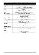
SPECIFICATIONS ................................................................................................................. 6


3.


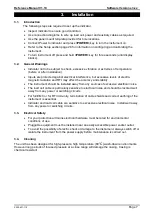
INSTALLATION .................................................................................................................... 7


3.1.


Introduction ................................................................................................................ 7


3.2.


General Warnings ...................................................................................................... 7


3.3.


Electrical Safety .......................................................................................................... 7


3.4.


Cleaning ..................................................................................................................... 7


3.5.


Cable Connections ..................................................................................................... 8


3.6.


DC Power (DC PWR + , DC PWR 

–) .......................................................................... 8


3.7.


Load Cell Connection ................................................................................................. 8


3.7.1.


Load Cell Signals and Scale Build .............................................................. 8


3.7.2.


4-Wire Connection ...................................................................................... 9


3.7.3.


6-Wire Connection ...................................................................................... 9


3.8.


Auxiliary Connections ................................................................................................. 9


3.8.1.


RS-232 Serial ........................................................................................... 10


3.8.2.


Remote Input ............................................................................................ 13


3.8.3.


Outputs ..................................................................................................... 14


3.9.


opto-LINK (Optional) ................................................................................................. 15


3.10.


Connecting Shields................................................................................................... 16


3.10.1.


Cable Shield Connection and Earthing ..................................................... 16


3.11.


Regulatory Sealing Requirements ............................................................................ 16


4.


DATA ENTRY ...................................................................................................................... 17


4.1.


Editing Annunciators ................................................................................................. 17


4.2.


Numeric Entry ........................................................................................................... 18


4.3.


Selections and Options ............................................................................................. 18


5.


BASIC OPERATION ........................................................................................................... 19


5.1.


Display ..................................................................................................................... 19


5.2.


Has a key been locked? ........................................................................................... 20


5.3.


Editing Function ........................................................................................................ 20


5.4.


Stability 

– What is a “Stable Error”? .......................................................................... 20


5.5.


POWER Key............................................................................................................. 20


5.6.


ZERO Key ................................................................................................................ 21


5.7.


TARE Key ................................................................................................................ 21


5.8.


GROSS/NET Key ..................................................................................................... 21


5.9.


PRINT Key ............................................................................................................... 22


5.10.


FUNCTION Key ........................................................................................................ 22


6.


CONFIGURATION............................................................................................................... 23


6.1.


General Setup Information ........................................................................................ 23


6.2.


Basic Weighing Terminology .................................................................................... 23


6.3.


Filtering Techniques ................................................................................................. 24


6.4.


Industrial vs  OIML and NTEP Modes ....................................................................... 24


Summary of Contents for CAS-X320

Page 1: ...IP69K Washdown Indicator Reference Manual 800 223 4227 www cas usa com U20151203 ...

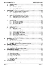
Page 2: ...ary Connections 9 3 8 1 RS 232 Serial 10 3 8 2 Remote Input 13 3 8 3 Outputs 14 3 9 opto LINK Optional 15 3 10 Connecting Shields 16 3 10 1 Cable Shield Connection and Earthing 16 3 11 Regulatory Sealing Requirements 16 4 DATA ENTRY 17 4 1 Editing Annunciators 17 4 2 Numeric Entry 18 4 3 Selections and Options 18 5 BASIC OPERATION 19 5 1 Display 19 5 2 Has a key been locked 20 5 3 Editing Function...

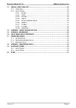
Page 3: ...UILD Scale Build 30 8 4 2 OPTION Scale Options 31 8 4 3 CAL Scale Calibration 32 8 4 4 SPEC Special Settings Menu 32 8 4 5 CLOC Clock 34 8 4 6 TEST Special Test Functions 35 8 4 7 FACTRY Factory Adjustment Menu 35 8 4 8 End Leaving Setup 36 9 SERIAL OUTPUTS 37 9 1 Serial Output Types 37 9 2 NET Network Communications 37 9 3 Auto Weight Format String 38 9 4 Menu Setup SERIAL Serial Communications O...

Page 4: ... HOLD and PEAK HOLD 46 13 2 6 SHOW T 47 13 2 7 HI RES 47 13 2 8 A TARE 47 13 2 9 CHECK W 48 14 APPENDIX TRADE SEALING DETAILS 49 15 APPENDIX DIMENSIONS 50 16 SETUP MENU QUICK REFERENCE 51 17 ERROR MESSAGES 53 17 1 Weighing Errors 53 17 2 Setup and Calibration Errors 54 17 3 Diagnostic Errors 55 18 APPENDIX RINWIRE PROTOCOL 56 19 GLOSSARY TERMS 59 19 1 List of Figures 59 19 2 List of Tables 60 20 I...

Page 5: ...rary isolated communications link to be established with a PC using an opto LINK cable which enables software upgrades and the use of computerised setup and calibration via the Viewer software Refer to opto LINK Optional page 15 for more information 1 1 Overview This instrument provides ZERO and TARE functionality as well as more setup options eg serial and setpoints and printing functionality It ...

Page 6: ...ns who are installing the instrument Communications Manual Contains details on the extended networking capabilities communications protocol 1 4 Document Conventions The following document conventions typographical are used throughout this Reference Manual Bold Text Bold text denotes words and phrases to note Key Key denotes a Keypad key Note In the Specifications section the symbol means less than...

Page 7: ...ble from 2 to 100 Full Scale Standard Power Input 12 to 24VDC 9 6 12 and 24V batteries 2 5 VA max ON OFF key with memory feature Variants AC AC Power supply 110 240VAC 50 60Hz in 12VDC 1 2A out Battery 12V battery pack rechargeable NiMH Case Materials PC Polyester alloy PBT Silicon Rubber SS304 Stand Packing Weights Basic Indicator 2 0kg Optical Data Communications Magnetically coupled infra red c...

Page 8: ...and stability The instrument should be installed away from any sources of excessive electrical noise The load cell cable is particularly sensitive to electrical noise and should be located well away from any power or switching circuits For full EMC or for RFI immunity termination of cable shields and correct earthing of the instrument is essential Indicator and load cell cable are sensitive to exc...

Page 9: ... it and the load cells If an optional battery pack is fitted then the supplied charging system must be used 3 7 Load Cell Connection 3 7 1 Load Cell Signals and Scale Build Very low output scale bases may be used but may result in some instability in the weight readings when used at higher resolutions Generally speaking the higher the load cell output or the lower the number of divisions the great...

Page 10: ...n accuracy The BUILD CABLE option must be set to 4 to allow for 4 wire connection Refer to CABLE 4 Wire or 6 Wire page 30 Figure 3 4 Wire Connections 3 7 3 6 Wire Connection The excitation and signal lines are connected the same as for a 4 wire installation The extra two wires Sense and should be connected to the Excitation and lines as close as possible to the load cell itself Typically these con...

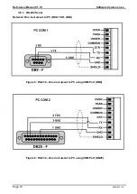
Page 11: ... 10 Software Versions 3 xx Page 10 X300 621 110 3 8 1 RS 232 Serial Network One Instrument to PC RXD TXD GND Figure 5 RS 232 One Instrument to PC using COM Port DB9 Figure 6 RS 232 One Instrument to PC using COM Port DB25 ...

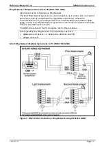
Page 12: ...e communications errors or for longer cable runs lower the baud rate to 4800 or 2400 and or use the Long Ring Network in Figure 8 below which uses a separate return path from the Last Instrument to the PC For DB25 connections at the PC connector refer to Figure 6 above When operating in a Ring Network the Instruments must have same serial port options i e baud parity data bits stop bits unique add...

Page 13: ...Instruments to PC RXD TXD GND The Long Ring Network layout can be used in situations where each leg of the cable run can be up to about 150 m 500 ft at 9600 baud If there are communications errors lower the baud rate to 4800 or 2400 Figure 8 RS 232 Long Cable Runs Ring Network using COM Port DB9 ...

Page 14: ...te input ie SPEC REM FN The SERIAL TYPE option must be set to AUTO PRINT or AUTO PR When using SERIAL TYPE of PRINT or AUTO PR the SPEC REM CHR must be set to an appropriate character that will not affect the printer This character will be sent repeatedly when the transmitter is idle regardless of the state of the DTR line Note The remote input will not function when in setup or when using the opt...

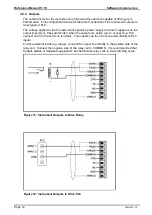
Page 15: ...l appears on the output lines Over Pass and Under when the outputs are active eg to connect to a PLC connect 24V to the common terminal The outputs can then be connected directly to PLC inputs To drive external loads eg relays connect the output line directly to the positive side of the relay coil Connect the negative side of the relay coil to COMMON It is recommended that fly back diodes or trans...

Page 16: ...from a PC The PC end of the opto LINK cable is a standard female DB9 connector or USB connector The instrument end of the cable consists of an infrared transceiver which attaches to the left side of the instrument display To facilitate a quick and simple connection the infrared transceiver is secured in place by a permanent magnet located within the head of the opto LINK Refer to opto LINK Activat...

Page 17: ...y be connected to earth via a single reliable link to avoid earth loops Where each instrument is separately earthed interconnecting cable shields should be connected at one end only This also applies to communications cable shields in Ring Networks refer to Short Ring Network and Long Ring Network connections under RS 232 Serial pages 11 and 12 Caution Some load cells connect the cable shield dire...

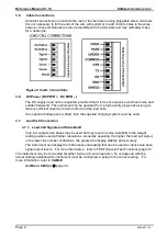
Page 18: ...f the editing annunciators When in Setup press the corresponding keypad key below the annunciator Figure 14 Editing Annunciators Editing Annunciator Key Name Description GRP ZERO Steps through the list of Groups ITM TARE Steps through the list of Items Press this key to accept changes and return to the menus Also refer to the OK description below SEL GROSS NET Moves the editing cursor in some edit...

Page 19: ... will be flashing Press SEL to advance to the next digit When the digit to edit is flashing press EDT repeatedly to cycle from 0 through 9 When the new digit to be set is flashing either press SEL to move to the next digit to edit and repeat the previous step or press OK or ITM to accept all of the displayed digits including the flashing digit and re display the menu item name 4 3 Selections and O...

Page 20: ...s NET weight MOTION Visible when the displayed reading is not stable OVER Visible when check weighing is enabled and the weight is above the target weight UNDER Visible when check weighing is enabled and the weight is below the target weight PASS Visible when check weighing is enabled and the weight is between the target weights ZERO BAND Visible when the displayed weight is within the zero dead b...

Page 21: ...ion page 31 for more information 5 5 POWER Key The POWER key is used to turn the instrument on and off If the PWR FN feature is set to UNITS then a short press of the POWER key will switch units To initially turn the instrument on press and hold the POWER key The display will show the following Display segments will light and then clear Software Version eg V1 0 Calibration Counter eg C 00010 Refer...

Page 22: ...ble range of the scale reducing the maximum weight that can be displayed The tare adjustment is stored when power is removed and is re used when next powered up Preset Tare This feature allows the operator to manually enter the tare weight When a preset tare weight is being used the instrument will display Pt before displaying the net weight Any printing of the tare weight will be followed by the ...

Page 23: ...mputer has been attached to the instrument and the manual print function has been selected the PRINT key will trigger an output of the current weight reading The PRINT prompt is displayed while waiting for the printer to accept data If the printer is offline the PRINT prompt will remain for a maximum of 10 seconds before the operation is cancelled Each weight printed is automatically added to an i...

Page 24: ...ary Terms page 59 Term Definition Units Units of measurement kilograms tonnes pounds etc Full Scale Total change in weight between zero gross load and full capacity gross load Resolution or Count by Smallest change in weight units that the display can show Total Number of Graduations Maximum number of display steps between zero gross load and full capacity gross load It is equal to full scale divi...

Page 25: ...ve trade certified standards For more information refer to the Calibration Counter section below and also to the USE Scale Use section page 31 for setup information The following table lists the operation differences for each of these modes Element Industrial OIML NTEP Underload 105 of full scale 1 or 2 of full scale depending on zero range setting 1 or 2 of full scale depending on zero range sett...

Page 26: ...al settings 6 6 Passcodes The instrument has two levels of passcodes to provide a security lock on accessing Setup via the keypad Full Setup Passcode Safe Setup Passcode The Full Setup passcode can also be used to access Safe Setup 6 6 1 Full Setup Passcode Setting a passcode for Full Setup restricts any access to Full Setup Refer to FULL PC Full Security Passcode for Digital Setup page 32 6 6 2 S...

Page 27: ...the Trade approved range Note It should not be assumed that just because the instrument has successfully calibrated a scale that the scale is correct for trade use Always check the scale build against the approval specification 7 1 Performing a Digital Calibration with Test Weights Figure 16 Chart Zero and Span Points to Interpolate Weight from Load Cell The Zero setting CAL ZERO specifies a gross...

Page 28: ... and repeat the operation 7 2 Performing a Calibration with Direct mV V Entry In applications where test weights are not easily available it is possible to calibrate the instrument directly by entering the mV V signal strength at Zero and full scale Span The Direct Zero setting CAL DIR ZER specifies a gross zero point for the scale The Direct Span setting CAL DIR SPN specifies the mV V signal stre...

Page 29: ...trument will respond with the message ENTRY DENIED Refer to Passcodes page 25 for more information Full Setup 1 Instrument on 2 Press and hold both the POWER and GROSS NET keys together for two seconds 3 Full Setup can also be entered by pressing a push button accessed from the rear of the instrument Refer to OPTIONS R ENTRY page 31 for more details WARNING All items in all menus will be enabled i...

Page 30: ...conds Option 3 Press the GRP key repeatedly When End displays press ITM or OK The instrument will beep and then display SAVING Software Version eg V1 0 Calibration Counter eg C 00010 Refer to Calibration Counter page 24 for more information R series instruments only The current weight will then display Warning If the power is interrupted while in setup ie by disconnecting the power cable or pressi...

Page 31: ...is set in weighing units eg kg t etc with the decimal point in place For example if a scale is to weigh 500 0 kg in 0 5 kg increments CAP is set to 500 0 and RES is set to 5 Range 000100 to 999999 Default 003000 RES Count by Resolution Sets the resolution or Count by of the display The resolution is the number by which the indicator will count Options are 1 2 5 10 20 50 or 100 Default 1 UNITS Weig...

Page 32: ...icator during power up The amount of weight that can be zeroed is limited to 10 of full scale Options are ON or OFF Default OFF Z TRAC Zero Tracking Sensitivity Zero tracking allows the display to adjust for minor changes in the zero balance of the scale When enabled the instrument will track weight readings within the zero dead band back to exactly zero at a maximum rate of 0 5 SLOW 3 MED or 10 F...

Page 33: ...all calibration critical settings in the BUILD OPTION and CAL menus back to factory defaults The instrument will prompt with Cont N Press EDT to change to Cont Y and OK to continue If Cont Y is chosen and then OK or ITM is pressed the instrument will display DONE to indicate that the operation has been completed 8 4 4 SPEC Special Settings Menu Settings within this group control features including...

Page 34: ...on network communications or any press of the keyboard is enough to keep the instrument powered on When operating on batteries the instrument will turn off after 30 minutes of inactivity even if set to Auto Options are NEVER Never power off automatically1 5 10 30 Auto time in minutes Default Auto B LIGHT Backlight Operation Sets the operation of the backlight When operating the backlight with batt...

Page 35: ...vel The indicator will assume it is on battery power when its input voltage is less than twice the low battery level for the selected battery voltage In the PWR mode the indicator will always assume it has external power Correct function of the low battery warning is dependent on correct setting of the battery voltage Battery Voltage Low Battery Level 9 6V 8V 12V 10V 24V 20V PWR NO BATTERY Li Ion ...

Page 36: ...rst case When accessing this item initially there should be no weight on the scale In OIML or NTEP modes this display is only active for five seconds before returning to the menu FRC OUT Force Outputs Forces each of the output drivers in turn All outputs turn OFF when leaving this step The EDT key will advance through each output ie ON 1 ON 2 and ON 3 Pressing OK will turn all outputs off and exit...

Page 37: ...talled on a different scale The instrument will prompt with Cont N Press EDT to change to Cont Y and OK to continue When Cont Y has been chosen the instrument will display DONE to indicate that the operation has been completed Restoring the factory options does not affect the calibration To reset the calibration to factory condition CAL FAC CAL must be used Refer to FAC CAL Restore Default Factory...

Page 38: ... a central computer or PLC o Instruments can be installed in a Ring Network Automatic Weight Output AUTO o The automatic output is normally used to drive remote displays a dedicated o Select between two standard formats master slave and custom Single Output SINGLE o The single output produces a single output with the formats selected It is used to drive remote displays a dedicated computer or PLC ...

Page 39: ...7 A seven character string containing the current weight including the decimal point If there is no decimal point then the first character is a space Leading zero blanking applies STATUS Provides information on the weight reading The characters G N U O M E represent Gross Net Underload Overload Motion Error respectively UNITS 3 A three character string the first character being a space followed by...

Page 40: ...it pattern and interface to be changed The display will show the current setting in the form n81 where each character has a meaning as shown below Options are N or O or E Parity bit N None O Odd E Even 8 7 Number of data bits 1 2 Number of stop bits D DTR handshake disabled or enabled Default n81 For most applications the default setting is applicable ADDRES Instrument Address Use this option to s...

Page 41: ...0 X300 621 110 I LOCK Print Interlock Sets the type of printing interlock to be used Options are NONE MOTION Printing is enabled every time the scale becomes stable RET Z Printing is enabled after the scale has returned to zero and is stable Default NONE ...

Page 42: ...ading units and G for Gross or N for Net Line 3 Alternate Gross or Net reading to line 2 Net reading when the Gross reading is displayed on the second line Gross reading when the Net reading is displayed on the second line Line 4 Tare reading when the Gross reading is displayed on the second line and the Gross reading units and G for Gross or N for Net 10 1 Printing Number of Pieces with Counting ...

Page 43: ... 0 kg T 000053 06 05 2003 15 21 13 3 kg G 0 0 kg N 0 0 kg T ITEMS 5 TOTAL 380 2 kg 10 3 Printing Total Weight and Number of Pieces Example print format when Counting is active and long press of PRINT key to print total number of items weight and quantity Note totals will be cleared and sequence number is not cleared 000054 06 05 2003 15 22 13 3 kg G 27 p 000055 06 05 2003 15 23 79 3 kg G 159 p 000...

Page 44: ...Count F0 H Current count if counting is turned on ID DA H Current print ID Time C0 H Current time Date BF H Current date Total Weight DB H Total of printed Display Weight since last summary print long press Total Count DD H Total number of pieces in Total Weight if counting turned on Items DC H Number of items printed since last summary print Standard Print short press 7F H Standard print Standard...

Page 45: ...mat of the output string is designed to allow a remote display to exactly copy the contents of the LCD including all of the annunciators and user prompts etc 11 7 Auto Output Speed There are four speeds to choose from 10 5 2 1Hz If using a remote input auto output speed must be set to 10Hz 11 8 Print Interlock The print interlock I LOCK sets the type of printing interlock to be used Printing is en...

Page 46: ...abled turned off ON Check weighing is enabled turned on Default OFF SRC Weight Source for check weighing The weight source determines the weight reading that is used for check weighing GROSS Use gross weight readings always DISP Use the displayed weight gross or net NET Use net weight readings always Default GROSS OVER Target for Over This is the target value for over This target provides the thre...

Page 47: ...hen show all segments of the display then clear the display again before returning to normal operation 13 2 3 COUNT Use this key to perform pieces counting Press the COUNT key to switch between weight display and counts display The instrument annunciator shows p for pieces To record a new sample do the following Tare off any containers Place the sample on the scale Press and hold the COUNT key for...

Page 48: ...ollowed by the number of items in the total After this TOTAL is displayed followed by the current total weight If the total weight is too large to display in six digits the weight is shown in two sections labelled with the upper six digits displayed before the lower six digits A long press of the PRINT key causes the total accumulated weight to be printed and then cleared The SERIAL TYPE option mu...

Page 49: ... will be displayed The next box can be placed on the scale and the process repeated 13 2 9 CHECK W The CHECK W key is used to gain access to the check weighing threshold values A short press of the key displays the threshold values while a long press enables editing of the threshold values A short press the CHECK W key will display Over followed by the over target followed by Under followed by the...

Page 50: ...14 Appendix Trade Sealing Details Attachment of Lead Seal through optional Captive Security Screws Please note that security screws are available as an option and that they are less corrosion resistant than the standard Captive Screws Back View showing cable locations ...

Page 51: ...e Versions 3 xx Page 50 X300 621 110 15 Appendix Dimensions Weight Indicator Dimensions in mm 1 inch 25 4 mm 3D View Front View Side View Bottom View Weight Indicator Wall Mount Dimensions in mm 1 inch 25 4 mm 3D View Stand Assembly ...

Page 52: ...n x 10 mode 32 CABLE 4 Wire or 6 Wire 32 OPTION USE Scale Use 33 FILTER Reading Average 33 MOTION Motion Detection 33 INIT Z Initial Zero on Startup 31 Z TRAC Zero Tracking Sensitivity 33 Z RANGE Allowable Zero Operating Range 33 Z BAND Zero Dead Band 33 R ENTRY Entry Means to Full Setup 33 CAL ZERO Zero Calibration 34 SPAN Span Calibration 34 DIR ZER Direct Zero Calibration 34 DIR SPN Direct Span...

Page 53: ...tions 41 ADDRES Instrument Address 41 AUT SPD Auto Output Speed 41 SHOW T Show Totals 41 RST CON Reset Printed Consecutive Number 41 I LOCK Print Interlock 42 CHECK W ENABLE 48 SRC Weight Source for check weighing 48 OVER Target for Over 48 UNDER Target for Under 48 CLOC FORMAT Date Format 37 YEAR Set Year 37 MONTH Set Month 37 DAY Set Day 37 HOUR Set Hour 37 MINUTE Set Minute 37 TEST SCALE Scale ...

Page 54: ...tion Resolution U The weight is below the minimum allowable weight reading Increase the weight or decrease the minimum allowable weight reading O The weight is above the maximum allowable weight reading Warning overloading may damage mechanical scale elements Check the condition of load cell connections Check for damaged load cell ZERO ERROR The weight reading is beyond the limit set for Zero oper...

Page 55: ...n point Points must be spaced by at least 2 of full scale from each other RES LO The scale build is configured for less than 100 graduations Check the resolution count by and capacity settings RES HIGH The scale build is configured for more than 30 000 graduations Check the resolution count by and capacity settings SPAN LO The load cell signal range span is too small for these settings Incorrect s...

Page 56: ...en set too low or too high Fix up scale build E0100 The digital setup information has been lost Re enter setup E0200 The calibration information has been lost Re calibrate E0300 All setup information has been lost Enter setup and calibrate E0400 The factory information has been lost Return for Service E0800 The EEPROM memory storage chip has failed Return for Service E2000 ADC Out of Range Error T...

Page 57: ...eceived from a module RESPONSE 40H Error Set to indicate that the data in this message is an error code and not a normal response 20H Reply Required Set by the master to indicate that a reply to this message is required by any slave that it is addressed to If not set the slave should silently perform the command 00H 1FH Module Address Valid addresses are 01 H to 1F H 1 31 00 H is the broadcast add...

Page 58: ...al Number Returns sensor serial number 0020H ADC Sample Number Read current sample number since last power on 32 bit 0021H System Status This register can be read to obtain the status of the instrument 32 status bits sent as 8 hex chars where 00020000 H Overload 00010000 H Underload 00008000 H Error see System Error 00004000 H SETUP menus active 00002000 H Calibration in progress 00001000 H Motion...

Page 59: ...e checksums use either a CRLF ASCII 13 ASCII 10 as a terminator or a semicolon ASCII There is no start of message delimiter Message Ring Network Enhancement Instruments with software revision V2 31 can be configured in a Ring Network via a M42xx module software revision 1 01 This requires the central computer to send additional framing characters Echo On DC2 ASCII 12 H and Echo Off DC4 ASCII 14 H ...

Page 60: ...o gross load and full capacity gross load ie the nominated total capacity of the scale It is always given in displayed weight units Resolution The smallest change in weight units that the display can show See also Count by RFI Radio Frequency Interference Ring Network A network of up to 31 Instruments connected to a central computer RS 232 Standard for communications hardware layers Step Response ...

Page 61: ...lay 14 Figure 12 Instrument Outputs to Drive PLC 14 Figure 13 opto LINK Attachment 15 Figure 15 Editing Annunciators 17 Figure 16 Display and Controls Illustration 19 Figure 17 Chart Zero and Span Points to Interpolate Weight from Load Cell 26 19 2 List of Tables Table 1 Industrial vs OIML and NTEP Modes 24 ...

Page 62: ...to LINK Activation 21 Group and Items 29 H HI RES 30 51 HOLD 46 HOUR 35 I Industrial vs OIML and NTEP Mode 24 INIT Z 31 51 K Key Functions 46 KEY FN 33 46 51 KEY LOC 33 Keypad Normal Operation 17 L LIVE WT 47 48 Load Cell Connection 8 Load Cell Signals 8 M Master Serial Output 43 44 MINUTE 35 MONTH 35 MOTION 20 31 51 N NONE 46 NVRAM 4 O OPTION 31 OPTION Scale Options 20 opto LINK 15 OVER 45 P Pass...

Page 63: ...Reference Manual V1 10 Software Versions 3 xx Page 62 X300 621 110 Notes ...

Page 64: ...Reference Manual V1 10 Software Versions 3 xx X300 621 110 Page 63 Notes ...

Reviews: