7
1.3 Environmental Conditions & Safety
1) Please avoid the following hostile conditions
2)
Environmental Protection
The scale should be installed in a dry and liquid free environment. When the scale is installed in
a high humidity or wet-type environment, be sure to avoid spilling or spraying directly on any
surface of the scale.
3)
Personal Safety
It is very important to be aware of personal safety whenever maintaining or operating this
equipment. We have tried to place warning labels and other indicators at the actual location on
the equipment where the danger is most likely to occur. Warnings and cautions that are
necessary for the safe operation of the scale are contained in this manual. Please, make sure
to read carefully ALL warnings and cautions before operating the scale.
4) Observe the following safety precautions
Shut the scale
OFF
and unplug the scale whenever you are changing the label roll or whenever
working in the printer bay.
The outlet that the scale is plugged into, should be properly grounded.
Whenever connecting or disconnecting
ANY
cables from the scale, be sure to hold the cables by
the end connector. Failure to do so may cause a short circuit.
Maintain a static-free work area.
The outlet used must have the proper voltage ratings.
Temperatures below or exceeding:
-10° C ~ 40° C (14° F ~ 104° F)
Ungrounded electrical outlet
Excessive vibration
Unstable or flimsy surface
Wind or fans functioning in direct
contact with weighing platform.
Shared electrical outlet
Direct sunlight
Dust or dirt
High humidity
Poor ventilation
Summary of Contents for CL5000 Series
Page 1: ...1 CL5000 Series CL5000 CL5500 Service Manual English Rev 2011 04 07 ...
Page 10: ...10 ...
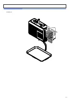
Page 14: ...14 Pole Type G Self service Type Double body Type CL5500 ONLY ...
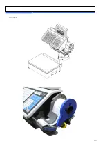
Page 16: ...16 TYPE III CL5000 G TYPE Ⅳ CL5500 D ...
Page 18: ...18 CL5000 H ...
Page 19: ...19 CL5500 D ...
Page 33: ...33 CL5500 D ...
Page 55: ...55 5 Servicing Parts Replacement ...
Page 56: ...56 ...
Page 78: ...78 8 Schematic Diagrams 8 1 1 System Block Diagram CL5000 B P R G S H ...
Page 79: ...79 8 1 2 System Block Diagram CL5500 D ...
Page 80: ...80 8 1 3 System Block Diagram CL5500 B P R H S ...
Page 81: ...81 8 2 1 Connection Diagram CL5000 B P R G S H ...
Page 82: ...82 8 2 2 Connection Diagram CL5500 D ...
Page 83: ...83 8 2 3 Connection Diagram CL5500 BPRHS ...
Page 84: ...84 8 3 I O Pin Connection CL5000 B P R G S H ...
Page 85: ...85 8 3 I O Pin Connection CL5500 ...
Page 86: ...86 9 Exploded Views 9 1 Double Body Type Head cover A ssy ...
Page 87: ...87 9 2 Double Body Type Cartridge A ssy ...
Page 88: ...88 9 3 Double Body Type Base bracket A ssy ...
Page 89: ...89 9 4 Double Body Type Door A ssy ...
Page 90: ...90 9 5 Double Body Type Head A ssy ...
Page 91: ...91 9 6 Double Body Type Tray A ssy ...
Page 92: ...92 9 7 Double Body Type Upper A ssy ...
Page 93: ...93 9 8 Double Body Type Platform A ssy ...
Page 94: ...94 9 9 Double Body Type Body A ssy ...
Page 95: ...95 9 10 Lan card ...


