70
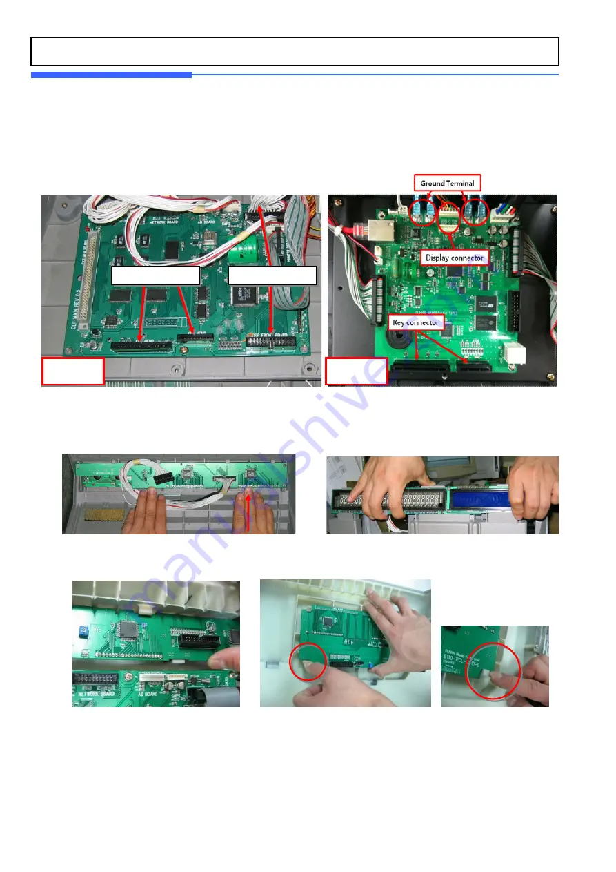
5.7 Display Replacement
1)
Turn power off and remove power cord
2)
Remove upper case (6.2)
3)
Remove keyboard and display cable of main board
4)
Remove front display board B,P,R type: lift display board at arrow side
Remove rear display board by lifting bottom part to unlock
5)
Remove Front, Rear display by unhook support part.
Key_Board Cable
Display Cable
CL5000
CL5500
Summary of Contents for CL5000 Series
Page 1: ...1 CL5000 Series CL5000 CL5500 Service Manual English Rev 2011 04 07 ...
Page 10: ...10 ...
Page 14: ...14 Pole Type G Self service Type Double body Type CL5500 ONLY ...
Page 16: ...16 TYPE III CL5000 G TYPE Ⅳ CL5500 D ...
Page 18: ...18 CL5000 H ...
Page 19: ...19 CL5500 D ...
Page 33: ...33 CL5500 D ...
Page 55: ...55 5 Servicing Parts Replacement ...
Page 56: ...56 ...
Page 78: ...78 8 Schematic Diagrams 8 1 1 System Block Diagram CL5000 B P R G S H ...
Page 79: ...79 8 1 2 System Block Diagram CL5500 D ...
Page 80: ...80 8 1 3 System Block Diagram CL5500 B P R H S ...
Page 81: ...81 8 2 1 Connection Diagram CL5000 B P R G S H ...
Page 82: ...82 8 2 2 Connection Diagram CL5500 D ...
Page 83: ...83 8 2 3 Connection Diagram CL5500 BPRHS ...
Page 84: ...84 8 3 I O Pin Connection CL5000 B P R G S H ...
Page 85: ...85 8 3 I O Pin Connection CL5500 ...
Page 86: ...86 9 Exploded Views 9 1 Double Body Type Head cover A ssy ...
Page 87: ...87 9 2 Double Body Type Cartridge A ssy ...
Page 88: ...88 9 3 Double Body Type Base bracket A ssy ...
Page 89: ...89 9 4 Double Body Type Door A ssy ...
Page 90: ...90 9 5 Double Body Type Head A ssy ...
Page 91: ...91 9 6 Double Body Type Tray A ssy ...
Page 92: ...92 9 7 Double Body Type Upper A ssy ...
Page 93: ...93 9 8 Double Body Type Platform A ssy ...
Page 94: ...94 9 9 Double Body Type Body A ssy ...
Page 95: ...95 9 10 Lan card ...


