16 Troubleshooting
56
16 Troubleshooting
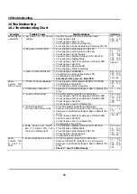
16.1 Troubleshooting Chart
Symptom
Possible Causes
Possible Solutions
Reference
1. No power to the Power
Supply.
§
Plug the Power Cord in to a working outlet.
§
Check/replace fuse.
§
Check/replace Power Cord.
§
Check/replace Main Power Switch.
§
Check/replace Power Supply Input Harness, CN1 PS.
3.3, 4.1,
14.4, 17.5,
18.1, 19.7
2. No power to Main PCB.
§
Check/replace Wire Harness, CN21 PS.
§
Check/replace Wire Harness, CN22 PS.
§
Check/replace Power Supply.
§
Check/replace Display Harness, J17/J18 M-PCB.
§
Check/replace Display Stalk.
§
Check/replace ADC Wire Harness, CON3 AD-PCB.
§
Check/replace AD-PCB.
§
Check/replace Network PCB.
§
Check/replace Printer Assembly.
2.1, 2.2, 3.3,
4.1, 4.2,
14.7 14.3,
14.4
14.6
17.4, 17.5,
18.1, 19.3,
19.6, 19.7
Scale will not
power ON.
3. Power to Main PCB is OK.
§
Check/replace all EPROMs.
§
Check/replace Memory Expansion PCB.
§
Check/replace Main PCB.
§
Also check
2.No power to Main PCB.
8.12, 12.10,
13.2, 13.3,
17.3, 17.5,
19.1, 19.6
1. “Printer Continuously Busy.”
§
Check/replace Printer System EPROM, U8 M-PCB.
§
Check/replace Main PCB.
§
Check/replace Printer Assembly.
10.5, 12.10,
14.3, 17.3,
19.6
2. “Calibrated mass error.”
§
Reprogram all Weight settings & Span calibrate the
scale.
7.1 ~ 7.4,
6.1
3. “Load Cell not ready.”
§
Check for platter or platform obstruction.
§
Check/replace ADC Wire Harness, CON3 AD-PCB.
§
Check/replace ADC Wire Harness, CON2 AD-PCB.
§
Check/replace AD-PCB.
§
Check/replace Load Cell Assembly.
2.1, 4.1, 6.1,
7.1 ~ 7.4,
12.3, 13.2,
13.5, 14.5,
19.5
4. “Zero Range Error.”
For more than 45 seconds.
§
Check for platter or platform obstruction.
§
Remove all items from platter and cycle power.
§
Reprogram all Weight settings & Span calibrate the
scale.
§
Check/replace ADC Wire Harness, CON2 AD-PCB.
§
Check/replace AD-PCB.
§
Check/replace Load Cell Assembly.
§
Check/replace Main PCB.
2.1, 4.1, 6.1,
7.1 ~ 7.4,
12.3,
14.1 ~ 14.5
17.4, 19.5
Scale
powers ON
with an error.
5. Scale beeps and “looks”
like it is turned ON, but
there is no display light.
§
Check/replace Display Harness, J17/J18 M-PCB.
§
Check/replace Display Stalk.
§
Check/replace Wire Harness, CN21 PS.
§
Check/replace Power Supply.
§
Check/replace Main PCB.
2.1, 2.2, 4.1,
4.2, 11.2,
14.3, 14.4,
14.7, 17.3,
19.3, 19.6
Scale
powers ON
& goes to
Zero.
1. Scale weight is inaccurate.
§
Check for platter or platform obstruction.
§
Remove all items from platter and cycle power.
§
Reprogram all Weight settings & Span calibrate the
scale.
§
Check
3.”Load Cell Not Ready.”
2.1, 4.1, 6.1,
7.1 ~ 7.4,
12.3, 14.3,
14.5, 17.4,
19.5
Summary of Contents for LP-2G
Page 2: ......
Page 8: ......
Page 11: ...1 General 3 Note Specifications are subject to change without notice ...
Page 46: ...11 Network Options 38 11 Network Options Refer to Network manual ...
Page 66: ...16 Troubleshooting 58 16 2 Versioning Changes ...
Page 69: ...17 Schematic Diagrams 61 17 3 Main PCB ...
Page 70: ...17 Schematic Diagrams 62 17 4 Ethernet Memory Expansion PCB ...
Page 71: ...17 Schematic Diagrams 63 17 5 Power Supply PCB ...
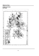
Page 72: ...18 Exploded Views 64 18 Exploded Views 18 1 Scale ...
Page 73: ...18 Exploded Views 65 18 2 Printer Assembly ...
Page 74: ......
Page 89: ...Appendix C 85 ...
Page 90: ...Appendix C 86 ...
Page 91: ...Appendix C 87 ...
Page 92: ...Appendix C 88 ...
Page 93: ...Appendix C 89 ...
Page 94: ...Appendix C 90 ...
Page 95: ...Appendix C 91 ...
Page 96: ...Appendix C 92 ...
Page 97: ...Appendix C 93 ...
Page 98: ...Appendix C 94 ...
Page 99: ...Appendix C 95 ...
Page 100: ...Appendix C 96 ...
Page 101: ...Appendix C 97 ...
Page 102: ...Appendix C 98 ...
Page 103: ...Appendix C 99 ...
Page 104: ...Appendix C 100 ...

