background image

3

INSTALLATION INSTRUCTIONS

Unpacking:

 Before assembling and installing your ceiling fan, remove all parts from the shipping cartons and check them 

against the parts listed here. Before discarding packaging material, be certain that all parts have been removed.

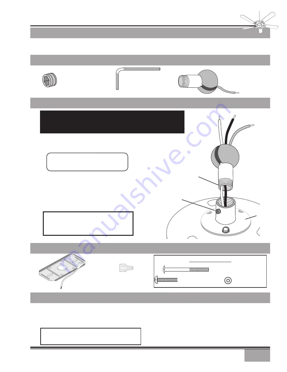
CEILINg HARDWARE

CROSSBAR mOUNT-

INg BRACKET

WIRE NUT (4)

FAN PREPARATION

gETTINg STARTED - CONTINUED

Installing a New Ceiling Fixture Outlet Box

If you do not have an existing fixture located where you wish 

to  place  your  Casablanca  fan,  an  approved  ceiling  fixture 

outlet box must be installed and wired.

Using Existing Ceiling Fixture Outlet Box

After  turning  the  power  OFF  at  its  source  (either  circuit 

breaker or fuse box), lower the old fixture and disconnect 

the wiring. Check the ceiling fixture outlet box to be sure 

that it is marked ‘

Approved for ceiling fan mounting

’. If it is 

not, a new box must be installed. 

PERMA•LOCk™ HARDWARE

warning: To reduce the risk of fire, electrical shock, 

or  personal  injury,  mount  to  outlet  box  marked 

acceptable for ceiling fan support.

addiTional hardware

CROSSBAR mOUNTINg

BRACKET SCREW 2

1

/

4

″ 

(2)

FLAT WASHER (2)

CROSSBAR mOUNTINg

BRACKET SCREW 1

(2)

M

etropolitan

®

ALLEN SET SCREW

¼

-20 x 

¼

(PRE-INsTALLED)

3mm

ALLEN WRENCH

Prepare for fan installation as follows:

Step  A.

  Route  the  wires  from  the  motor  through  the 

Perma•Lock™ downrod and ball assembly.

Step B.

 Using the provided allen wrench, loosen the set screw 

several turns to allow installation of the downrod.  Thread the 

downrod into the motor coupling until it stops turning, this 

will take at least four and a half full turns. 

Step C.

 Securely tighten the set screw with the provided allen 

wrench to ensure safe operation of your fan.

Tip:

 The downrod has a tapered thread 

that is designed to lock completely when 

correctly installed.  

CAUTION: Failure to fully lock in the down-

rod before securely tightening the allen set 

screw may cause the fan to separate from 

the downrod during normal operation!

mOTOR

COUPLINg

TAPERED

THREAD

mOTOR

WIRES

gROUND

WIRE

ALLEN

SET SCREW

DOWNROD

& BALL

ASSEmBLY

DOWNROD & BALL

ASSEmBLY

imporTanT safeTy informaTion!

BEFORE STARTINg THE INSTALLATION OF YOUR CEILINg FAN, INSTALL THE 

THREADED DOWNROD INTO THE MOTOR COUPLINg AND LOCk THE AssEMbLy

Summary of Contents for 64xxT

Page 1: ...e reference SAFETY FIRST introduction 1 mounting recommendations 2 fan INSTALLATION 3 control features INTELI TOUCH2 OPERATION 8 troubleshooting INTELI TOUCH2 11 BEFORE YOU START PN 4843010 AT0109 CAUTION To avoid possible electrical shock make certain that electricity is turned off at the circuit breaker or fuse box before attempting any installation procedure CAUTION RISK OF ELECTRICAL SHOCK All...

Page 2: ...es must be a minimum of 7 above the floor Do not locate the fan in a doorway or above a swinging door In any installation the tips of the blades must be at least 18 from the wall in order to provide suf ficient clearance for the blades In bedrooms fans work best when mounted above the foot of the bed Over pool tables be sure to provide plenty of clearance to avoid damage from pool cues In low ceil...

Page 3: ...e for ceiling fan support additional hardware CROSSBAR MOUNTING BRACKET SCREW 21 4 2 FLAT WASHER 2 CROSSBAR MOUNTING BRACKET SCREW 1 2 Metropolitan ALLEN SET SCREW 20 x pre installed 3mm allen wrench Prepare for fan installation as follows Step A Route the wires from the motor through the Perma Lock downrod and ball assembly Step B Using the provided allen wrench loosen the set screw several turns...

Page 4: ...ssbar mounting bracket center hole Attach the bracket with ground wire and ridges down to the Approved For Ceil ing Fan Installation ceiling fixture outlet box with the outlet box mounting hardware Tighten the screws firmly being careful not to bend the bracket by over tightening ceiling wiring crossbar mounting bracket flat washer green ground wire ceiling fan approved wiring box ridge side down ...

Page 5: ...UTRAL wire in ceiling fixture outlet box Secure with wire nut BLACK power wire from fan to BLACK power wire in ceiling outlet box Secure with wire nut 2 WHITE WIRES 2 BLACK WIRES 3 GREEN WIRES Step 5 Tuck the wires into the canopy with the wire nuts pointed upwards so that the WHITE and BLACK wires are on opposite sides of the canopy and all wires are clear of the canopy opening Step 6 Install can...

Page 6: ...e Hand tighten securely ASSEMBLE blade holder BLADE BADGE STYLE BLADE HOLDER BLADE BLADE BADGE BLADE HOLDERS HARDWARE BLADE SCREW 4 PER BLADE BLADE HOLDER SCREW 2 PER BLADE BLADE SCREW 4 PER BLADE 4 5 Blade Combination Flywheel Your Casablanca fan includes our 4 5 combination fly wheel This flywheel accomodates your preference to use either 4 or 5 blades on your fan If you desire a 4 blade fan loc...

Page 7: ... plate Carefully slide the switch housing into the mount so that the threaded holes are directly behind the clearance holes Step 12 Install the three screws removed in Step 10 Tighten securely by hand only Step 10 Remove the three screws on the mounting plate Set aside for Step 12 preparing to install switch housing cap Mounting Plate Screws 3 Metropolitan ...

Page 8: ...from the switch box to expose the wire connections 3 Determine which wire is connected to the common ter minal of the 3 way switch The terminal will be marked on switch 4 Remove the wire from the common terminal of the 3 way switch Connect this wire to the remaining black white striped wire on the W 32 control Secure this splice with a wire nut 5 Remove the two remaining wires from the 3 way switc...

Page 9: ...vel of speed turn the fan on by pressing less than one second To lower speed turn fan off then on by pressing and holding the button until the desired speed is reached When the fan is on you may increase the speed by pressing and holding the button until the desired speed is reached then release it The direction of airflow can be changed from downward to upward or from upward to downward To revers...

Page 10: ...es the speed of the fan each two hour interval to compensate for the cooling night air To enter the Fan Minder Program 1 Turn the POWE off for at least three seconds 2 Turn the POWE on 3 Immediately operate the buttons in the following sequence 4 The fan controller will respond with three descending tones A timer is now initiated and the fan will reduce one speed for each two hour interval The fan...

Page 11: ... switch position Check all wire connections making sure the power is turned off during this inspection FAN WOBBLES OR SHAKES Be sure canopy pin is properly set into the slot on the ball EXCESSIVELY Check the screws holding the blade holders to the fan motor Tighten as necessary Check the angle of the blades to make sure that a blade holder has not been bent during installation FAN NOISY DURING Che...

Page 12: ...tor XLP 2000 Blade Span 44 54 Blade Iron Pitch 15 No of Blades 5 Technology Inteli Touch W 32 Airflow 6 003 cfm Electricity Use 119 watts Airflow Efficiency 50 5 cfm watt Performance data is for fan only No lighting wattage is included Measurements taken with 21 basic blades NOTE Dimension B includes light fixture and glass ...

Page 13: ...13 ...

Reviews: