background image

1

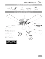
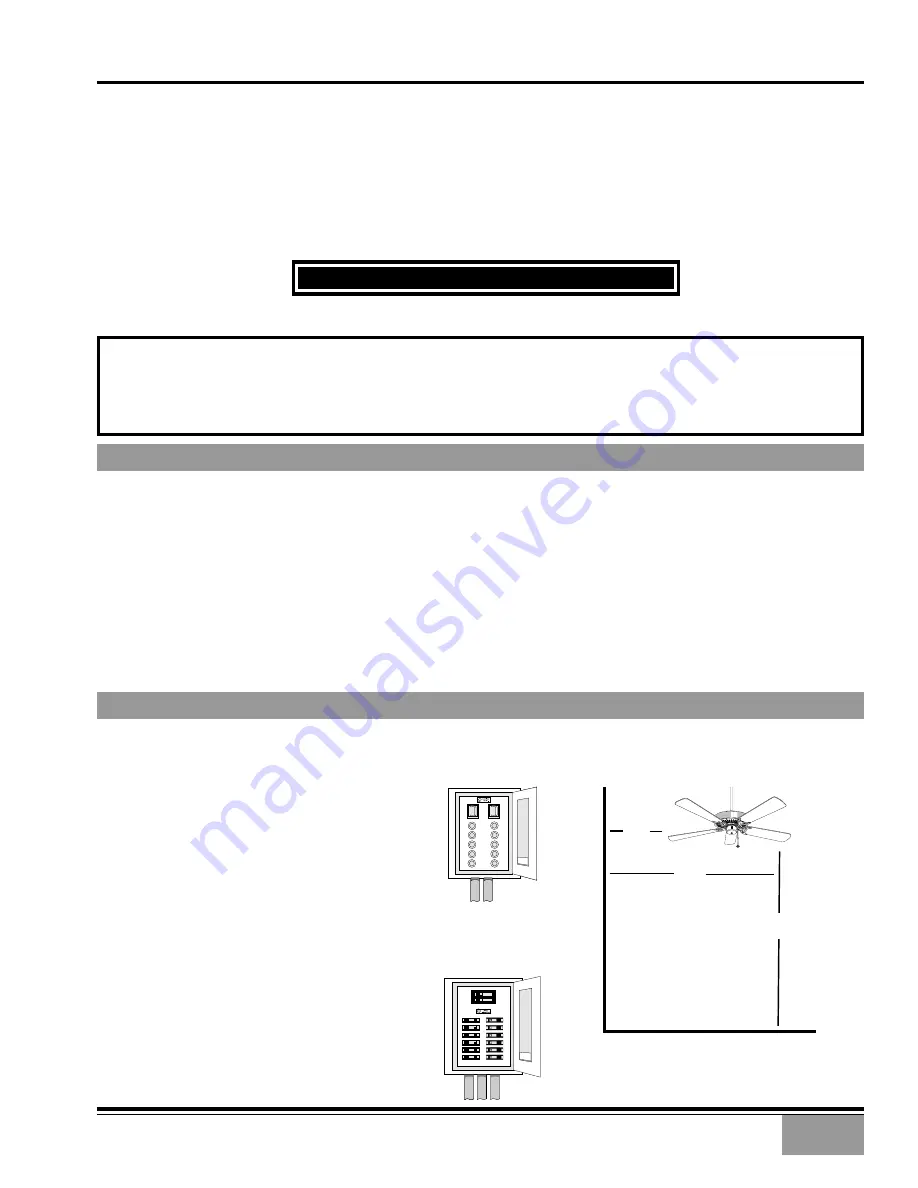
CIRCUIT BREAKER

(TRIP BREAKER FOR THE

CIRCUIT YOU WILL BE

WORKING ON)

FUSE BOX

(REMOVE FUSE FOR THE

CIRCUIT YOU WILL BE

WORKING ON)

The blades in each pack are matched for equal
weight to assure smooth fan operation. If
more than one fan is being installed, be
careful not to mix blades from different
cartons.

Inspect the contents of your carton for
possible shipping or handling damage and
report any such damage directly to your
authorized Casablanca dealer.

It is always a good idea to have an assistant
to help with the installation.

When cleaning, painting, or working near
your fan, be very careful of the fan and blades.
Always turn the power OFF to the ceiling fan
before servicing it, working on it, or replacing
light bulbs.

Never insert anything into the path of the
fan blades while the fan is in operation.

• Never install a fan over a pool or spa.

Never operate a fan that has been damaged
in any way. Contact Casablanca Fan Company
by calling toll free 1-888-227-2178, or
contact your local authorized Casablanca
dealer for assistance in obtaining service.

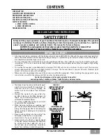
CONTENTS

READ AND SAVE THESE INSTRUCTIONS

All wiring must be in accordance with the National Electric Code ANSI/NFPA 70-1993 and the appropriate local electrical
codes. The National Electric Code requires proper grounding as a precaution against electrical shock. A qualified electri-
cian should be consulted if you are unsure.

• This fan is designed to be installed on an existing electrical outlet box. The outlet box must be UL Listed for ceiling fan

installations, if it is not, a new box must be installed. Casablanca extension poles are available for sloped or high ceiling
installations.

This ceiling fan requires a grounded electrical supply of 120 VAC, 60 Hz and a minimum 15 amp circuit. The maximum
current requirement for the fan with light fixture is 3.8 amps. The fan uses about 1 amp or 100 watts. Maximum light
current is 2.8 amps or 340 watts of lighting.

Where wire nuts are employed, be sure all bare wires are within the connectors. When installing the canopy hatch, make
sure all wires are within the canopy and that no wires are being pinched.

For best performance and for your warranty to be valid,

use only genuine Casablanca blades, light fixtures, and accessories.

SAFE USE

Safety and the proper operation of your Casablanca fan both require a thorough knowledge of the product

and proper installation; therefore, before attempting to install and operate your Casablanca fan, read this

owner’s manual completely and carefully. Retain this manual for future reference.

SAFETY FIRST

INTRODUCTION  . . . . . . . . . . . . . . . . . . . . . . . . . . . . . . . . . . . . . . . . . . . . . . . . . . . . . . . . . . . . . . . . . . . . . . 1

MOUNTING RECOMMENDATIONS  . . . . . . . . . . . . . . . . . . . . . . . . . . . . . . . . . . . . . . . . . . . . . . . . . . . . . . . . . . 2

PREPARATION INSTRUCTIONS  . . . . . . . . . . . . . . . . . . . . . . . . . . . . . . . . . . . . . . . . . . . . . . . . . . . . . . . . . . . 3

FAN INSTALLATION (USA) . . . . . . . . . . . . . . . . . . . . . . . . . . . . . . . . . . . . . . . . . . . . . . . . . . . . . . . . . . . . . . . 4

FAN INSTALLATION (OUTSIDE USA)  . . . . . . . . . . . . . . . . . . . . . . . . . . . . . . . . . . . . . . . . . . . . . . . . . . . . . . . . 10

CONTROL FEATURES:

3-SPEED CONTROL WIRING  . . . . . . . . . . . . . . . . . . . . . . . . . . . . . . . . . . . . . . . . . . . . . . . . . . . . . . . . . . . 14

3-SPEED OPERATIONS . . . . . . . . . . . . . . . . . . . . . . . . . . . . . . . . . . . . . . . . . . . . . . . . . . . . . . . . . . . . . . . 15

TROUBLESHOOTING  . . . . . . . . . . . . . . . . . . . . . . . . . . . . . . . . . . . . . . . . . . . . . . . . . . . . . . . . . . . . . . . . . . . 16

BEFORE YOU START

             PN 8443011 AT

10

08

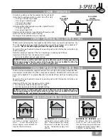
CAUTION: To avoid possible electrical shock, make certain that electricity is turned off at
the circuit breaker or fuse box before attempting any installation procedure.

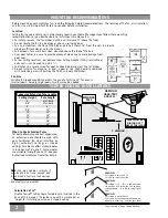
18"

84"

70"

Summary of Contents for FOUR SEASONS III

Page 1: ...re This fan is designed to be installed on an existing electrical outlet box The outlet box must be UL Listed for ceiling fan installations if it is not a new box must be installed Casablanca extension poles are available for sloped or high ceiling installations This ceiling fan requires a grounded electrical supply of 120 VAC 60 Hz and a minimum 15 amp circuit The maximum current requirement for ...

Page 2: ...ust be a minimum of 7 above the floor Do not locate the fan in a doorway or above a swinging door In any installation the tips of the blades must be at least 18 from the wall in order to provide sufficient clearance for the blades In bedrooms fans work best when mounted above the foot of the bed Over pool tables be sure to provide plenty of clearance to avoid damage from pool cues In low ceiling l...

Page 3: ...to be sure that it is marked Approved for ceiling fan mounting If it is not a new box must be installed WARNING To reduce the risk of fire electrical shock or personal injury mount to outlet box marked acceptable for ceiling fan support using the mounting hardware provided with the outlet box CAUTION When removing the shrink wrap be careful not to scratch the blades NOTE The fan weight is 17 pound...

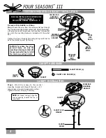
Page 4: ... HATCH CANOPY LOCK WASHER 4 CANOPY SCREW 4 APPROVED OUTLET BOX HARDWARE NOTE On sloped ceilings align the canopy opening towards the top or room peak Proceed with installation as follows Step 1 Route the wires from the ceiling outlet box through the crossbar mounting bracket center hole Attach the bracket with ground wire and ridges down to the ceiling fixture outlet box with the mounting hardware...

Page 5: ......

Page 6: ... NUT W 8 CONNECTIONS 3 GREEN WIRES 3 GREEN WIRES 2 WHITE WIRES BLACK RED WIRES BLUE YELLOW WIRES PULL CHAIN OR W 4 CONNECTIONS CANOPY HATCH INSTALLATION Step 9 Tuck the wires into the canopy with the wire nuts pointed upwards so that the WHITE and BLACK wires are on opposite sides of the canopy and all wires are clear of the canopy opening Step 10 Install canopy hatch with the last canopy screw an...

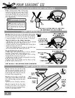
Page 7: ...7 FOUR SEASONS III blade blade holder hardware FIBER FLAT WASHER FIBER FLAT WASHER PAGE 14 ...

Page 8: ...wn tucking the exposed wires into the fitter and aligning the screw holes Using the three screws attach the light kit fitter to the fan Screw the two 60 Watt lightbulbs onto the light kit fitter Fish the pullchain through the center holes of the metal disk of the light kit fitter Continue to fish the pullchain through the bowl and cap Fit bowl and cap around the light kit fitter Using the finial a...

Page 9: ...9 FOUR SEASONS III ...

Page 10: ...LATION OUTSIDE THE USA EXCLUDING MODELS ENDING IN E OUTSIDE USA MOUNTING SECONDARY SUPPORT PARTS TO OUTLET BOX OUTLET ADAPTOR PLATE JOIST OR BEAM OUTLET BOX 8 32 X 21 4 1 SCREW 6 OUTLET BOX CABLE OUTSIDE USA SECONDARY SUPPORT INSTALLATION PARTS If you do not have an existing fixture located where you wish to place your Casablanca fan a new ceiling fixture outlet box must be installed use an outlet...

Page 11: ...f the Cable Clamp and the end of the Secondary Support Cable with electrical tape CABLE CLAMP SCREW Step 9 Pull the cable through the other side of the fan to snug the cable clamp This makes it easier to install the switch housing Step 10 Remove the three mounting screws from the switch housing plate Keep them for the next step MOUNTING SCREW 3 TAPED OVER CABLE CLAMP SCREW FOUR SEASONS III OUTSIDE...

Page 12: ...the bare ends of the wiring together FAN CABLE CANOPY OUTLET BOX CABLE SPRING LOCK CANOPY SCREW CANOPY LOCK WASHER FEED OUTLET BOX CABLE AND OUTLET BOX WIRES THROUGH CANOPY OPENING FAN CABLE SPRING LOCK HOOK BALL SLOT PIN White wire from fan to white NEUTRAL wire in ceiling outlet box Black wire and blue wire from fan to black or red POWER wire in ceiling outlet box Green leads from crossbar mount...

Page 13: ...ors for the wire nuts shown throughout this manual FAN AND OUTLET CABLES SECURED BY SPRING LOCK HOOK WIRE NUTS INSTALLED BLADE SCREW 3 PER BLADE FLAT WASHER 3 PER BLADE BLADE HOLDER SCREW 2 PER BLADE BLADE HOLDER BLADE SCREW 3 PER BLADE FLAT WASHER 3 PER BLADE Step 18 Attach the blades to the blade holders with the three blade screws and flat washers provided for each blade Hand tighten securely S...

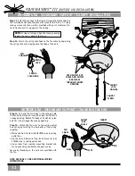
Page 14: ... 4 different speed settings No light fixture is used Set the FAN pull chain switch to the HIGH speed setting No changes in household or fan wiring are required The fan may be turned ON and OFF by the W 4 wall control CAUTION Failure to set the pull chain speed to HIGH can result in faulty operation of the fan and damage to the W 4 wall control To confirm fan is set to HIGH Turn W 4 fan speed switc...

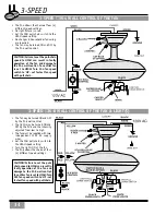
Page 15: ...s designed to replace a standard wall switch and wall boxes with a depth of 2 or greater Requires two hot leads from wall box to ceiling wiring box To install a W 8 wall control in place of an existing wall switch follow the instructions on the W 8 package Operation of the fan from the wall switch is simple 1 Turn the upper knob to the desired fan speed 2 Turn the lower knob to the desired light s...

Page 16: ...nty FAN WILL NOT START Check main circuit fuses circuit breakers or wall switch position Check all wire connections making sure the power is turned off during this inspection Check that reverse switch is not set in center of throw FAN WOBBLES OR SHAKES Be sure canopy pin is properly set into the slot on the ball EXCESSIVELY Check the screws holding the blade holders to the flywheel or direct drive...

Page 17: ...ight 17 lbs Motor 172mm x 12mm Direct Drive Blade Span With 52 Blade Pitch 13 No of Blades 5 Technology 3 Speed Lightbulbs 2 60 watt candelabra bulbs Airflow 5 100 cfm Electricity Use 80 watts Airflow Efficiency 74 3 cfm watt Performance data is for fan only No lighting wattage is included NOTE Dimension B includes light fixture and glass ...

Reviews: