
16
Fan Finishes
• For cleaning, a soft brush or lint-free cloth should be used to prevent scratching the finish.
• A vacuum cleaner brush nozzle can remove heavier dust.
• Surface smudges or an accumulation of dirt and dust can be removed easily using a mild detergent and slightly dampened
soft cloth. An antistatic agent may be used, but
never use abrasive cleaning agents
as these will damage the finish.
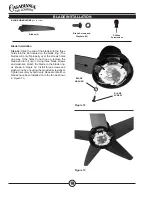
Blades
• Wood-finish blades should be cleaned with a furniture polishing cloth. Occasionally, a light coat of furniture polish may be
applied for added protection and luster.
• For painted and high-gloss blades, surface smudges or an accumulation of dirt and dust can be removed easily using a
mild detergent and slightly dampened soft cloth. An antistatic agent may be used, but
never use abrasive cleaning agents
as these will damage the finish.
• Warning: To reduce the risk of personal injury, do not bend the blade brackets when installing the brackets, balancing the
blades, or cleaning the fan. Do not insert foreign objects in betweeen rotating fan blades.
No Need for Lubrication
•
Never lubricate this fan!
The precision motor at the heart of your Casablanca fan features sealed bearings that are lubricated
for life.
• Do not attempt to oil the motor.
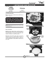
Changing Lightbulbs
• Be sure to turn the power to OFF at the wall switch or circuit breaker before changing lightbulbs.
• Replace bulbs with the same type as you removed from the light fixture.
• The maximum wattage rating for this fan’s light kit is 100 watts for the light.
CARE RECOMMENDATIONS
For questions or to locate the nearest Casablanca Authorized Service Center,
call toll-free 1-888-227-2178 or visit us at www.CasablancaFanCo.com
This device complies with RSS-210 of Industry Canada. Operation is subject to the following two conditions: (1) this device may not cause interference,
and (2) this device must accept any interference, including interference that may cause undesired operation of the device.
1. This device complies with part 15 of the FCC Rules. Operation is subject to the following two conditions: (1) this device may not cause harmful inter-
ference, and (2) this device must accept any interference received, including interference that may cause undesired operation.
2. This equipment has been tested and found to comply with the limits for a Class B digital device, pursuant to Part 15 of the FCC Rules. These limits are
designed to provide reasonable protection against harmful interference in a residential installation. This equipment generates, uses and can radiate radio
frequency energy and, if not installed and used in accordance with the instructions, may cause harmful interference to radio communications. However
there is no guarantee that interference will not occur in a particular installation. If this equipment does cause harmful interference to radio or television
reception, which can be determined by turning the equipment off and on, the user is encouraged to try to correct the interference by one or more of
the following measures: Reorient or relocate the receiving antenna, Increase the separation between the equipment and receiver, Connect the equip-
ment into an outlet on a circuit different from that to which the receiver is connected. Consult the dealer or an experienced radio/TV technician for
help. Note: Any changes or modifications to the transmitter or receiver not expressly approved by Casablanca Fan Company may void one’s authority
to operate this remote control.


