

I
sotope
®
3
C
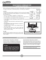
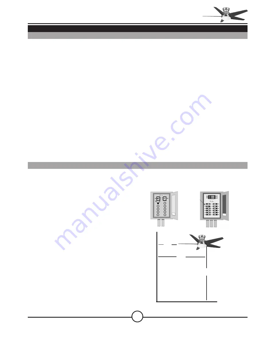
ircuit Breaker
(Trip breaker for the
circuit you will be
working on)
Fuse Box
(Remove fuse for the
circuit you will be
working on)
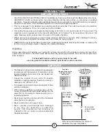
18"
84"
70"
SAFE USE
INTRODUCTION
BEFORE YOU START
from bottom
edge of blade
to floor
from wall to
end of blade
Dimensions indicated are the minimum
allowable for proper installation.
•
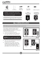
CAUTION: RISK OF ELECTRICAL SHOCK! Installation is to be in accordance with the National Electrical Code,
ANSI/NFPA 70-1999, and local codes. If you are unfamiliar with the wiring codes, you should use a qualified
electrician. To avoid overheating and possible damage to other equipment, do not install control to a receptacle,
fluorescent light fixture, motor-operated appliance, or transformer-supplied appliance.
• This fan is designed to be installed on an existing electrical outlet box. The outlet box must be UL Listed for
ceiling fan installations. If it is not, a new box must be installed.
•
This ceiling fan requires a grounded electrical supply of 120 VAC, 60 Hz and a minimum 15 amp circuit. The
maximum current requirement for the fan with light fixture is 1.67 amps. The fan uses about .83 amp or 100
watts. Maximum light current is about .83 amps or 100 watts of lighting.
•
Where wire nuts are employed, be sure all bare wires are within the connectors. When installing the canopy,
make sure all wires are within the canopy and that no wires are being pinched.
•
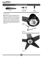
WARNING: Do not bend the blade brackets when installing the brackets, balancing the blades, or cleaning the
fan. Do not insert foreign objects in between the rotating fan blades.
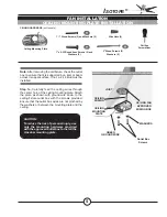
Unpacking
Before assembling and installing your ceiling fan, remove all parts from the shipping cartons and check them
against the parts listed in the Parts Guide. Before discarding packaging materials, be certain that all parts have
been removed.
For best performance and for your warranty to be valid,
use only genuine Casablanca blades, light fixtures, and accessories.
•
The blades in each pack are matched for equal weight
to assure smooth fan operation. If more than one fan
is being installed, be careful not to mix blades from
different cartons.
•
Inspect the contents of your carton for possible
shipping or handling damage. If parts are missing or
damaged, call 1-888-227-2178.
•
It is always a good idea to have an assistant to help
with the installation.
•
When cleaning, painting, or working near your fan,
be very careful of the fan and blades. Always turn the
power OFF to the ceiling fan before working on it or
replacing lightbulbs.
•
Never insert anything into the path of the fan blades
while the fan is in operation.
• Never install a fan over a pool or spa.
•
Never operate a fan that has been damaged
in any way. For assistance in obtaining
service, call Casablanca Fan Company at
1-888-227-2178 or contact your local authorized
Casablanca dealer.
from wall to
center of fan


