background image

8

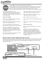
MOUNTING BRACKET INSTALLATION (CONT.)

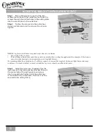
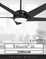
Step 1.  Place a flat washer on each of the two 

screws that came with the outlet box and pass the 

screws through the slotted holes in the ceiling plate 

into the screw holes in the outlet box.
Step 2.  Tighten the screws into the outlet box; 

do not use lubricants on the screws. Do not over 

tighten.

Joist

Ceiling Fan 
Approved 
Wiring Box

Washer

Outlet 
Box 
Screw

Joist

Ceiling Fan 
Approved 
Wiring Box

Washer

Outlet 
Box 
Screw

Step 3.  Install the lag screw if needed. Pass the 

lag screw with the large washer attached through 

the center hole of the ceiling plate and screw 

into the guide hole. Tighten until the outlet box 

is mounted firmly to the beam. This box must be 

secured to the ceiling firmly. 

NOTE:


 Lag Screw installation is required only under two conditions:

•  Fan weighs 36 lbs. or more 

•  If the existing ceiling fixture outlet box needs to be modified for a ceiling fan application (for example, if the house is 

not new construction and you are replacing an existing light fixture). 

We recommend that the ceiling box be of sufficient capacity to support the weight of the fan and light fixture under any 

conditions. If in doubt whether you need to install the lag screw, consult a qualified electrician.

Summary of Contents for Stealth DC C45G11B

Page 1: ...C45GxxxB Stealth dc O W N E R S M A N U A L...

Page 2: ...y contain blisters seeds or thin lines These characteristics are not defects but substantiate that this is handblown and handcrafted glass All costs of installing removing and reinstalling the product...

Page 3: ..._______2 Introduction________________________________________________________________________5 BeforeYou Start 5 Safe Use 5 Mounting Recommendations 6 Sloped Ceiling Installation 6 Fan Installation___...

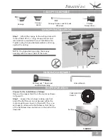
Page 4: ...Washer 7 8 32 Truss Screw Ceiling Plate 8 8 Flat Washer 9 8 Split Lockwasher 10 8 32 round Screw Canopy Screw 11 Large Wire Nut Orange 12 3 0 Pipe Assembly Blade Iron Set Pre Installed 14 Blade Tip Bl...

Page 5: ...24 203 77745 03 695 77745 03 214 1 93426 05 203 93426 05 695 93426 05 214 5 85061 01 203 85061 01 695 85061 01 214 1 G0706 03 000 G0706 01 000 G0706 02 000 11 1 G0113 72 000 G0113 73 000 G0113 74 000...

Page 6: ...o install them Before discarding packaging materials be certain that all parts have been removed Use a clean dry paintbrush to remove small Styrofoam pieces that may remain after unpacking Do not brus...

Page 7: ...pinched WARNING Do not bend the blade brackets when installing the brackets balancing the blades or cleaning the fan Do not insert foreign objects in between the rotating fan blades Unpacking Before a...

Page 8: ...ng Angle Use the tear off Ceiling AngleTemplate card inserted in this manual It provides you with a simple go or no go for installing your fan on a sloped ceiling 7 minimum When to Use Extension Poles...

Page 9: ...is 33 pounds WARNING To reduce the risk of fire electrical shock or personal injury mount to outlet box marked Acceptable Fan Support of 22 7 kg 50 lbs or less using the mounting hardware provided wit...

Page 10: ...ith the large washer attached through the center hole of the ceiling plate and screw into the guide hole Tighten until the outlet box is mounted firmly to the beam This box must be secured to the ceil...

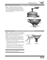
Page 11: ...ling NOTE On sloped ceilings align the canopy opening with the top or peak of the room HANGING HARDWARE FAN PREPARATION PAPER MOTOR SHIELD FIGURE 1 Prepare for fan installation as follows Remove the p...

Page 12: ...a tapered thread that is designed to lock completely when installed correctly Tighten the set screw as shown in Figure 4 with the included allen wrench to ensure safe operation of your fan If it is t...

Page 13: ...Step 3 Attach the fan wires to the ceiling fixture outlet box wiring by placing the bare ends of the wires side by side and then securing with a wire nut Test that the connection is secure by pulling...

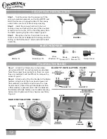
Page 14: ...ANOPY HATCH INSTALLATION FIGURE 4 FIGURE 1 BLADE HOLDER BLADE ATTACHING THE BLADES Step 1 Attach the 5 blade tips to the blades using two 6 32x1 8 round head screws provided Note the screws have lockt...

Page 15: ...ach tab Step 4 Turn power back ON at the circuit breaker or fusebox Step 5 This completes the installation of the fan Step 1 Open battery compartment door by pressing down and sliding battery door dow...

Page 16: ...circuit breaker or fuse box turn the power back on for the fan whose frequency you are changing Step 6 Within 60 seconds of restoring power push and hold the SET button in the battery compartment for...

Page 17: ...h and then change directions To turn the lights off and on press and release the button for less than one second To dim the light Press and hold the button for more than 1 second The light will come o...

Page 18: ...help Note Any changes or modifications to the transmitter or receiver not expressly approved by Casablanca Fan Company may void one s authority to operate this remote control PROBLEM POSSIBLE REMEDIES...

Page 19: ...eight 33 lbs Motor DC Blade Span 54 Blade Iron Pitch 14 No of Blades 5 Technology DC Control Lightbulb 1 100 watt halogen lightbulb Airflow 6 553 cfm Electricity Use 30 watts Airflow Efficiency 218 46...

Page 20: ...PN C4543001_DC 7130 GOODLETT FARMS PKWY SUITE 400 MEMPHIS TN 38016 1 888 227 2178 WWW CASABLANCAFANCO COM...

Reviews: