
19
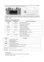
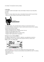
. DISTANCE
. CALORIES
. PULSE
Use UP & DOWN to set values and confirm your selection by ENTER button.
Press START/STOP
button
to start workout.
As soon as one of the set values reach the preset Target, the computer will alarm with Bi-bi sound and
stop.
-You can adjust the level of resistance on the
pedals
while exercising by pressing UP and DOWN keys.
The newly set level value will be shown in the profile(default value is Level 1).
-Press START/STOP
button
to end exercising. All exercising value will remain
.
-Press RESET to reverse to workout selection menu.
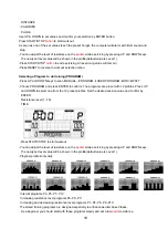
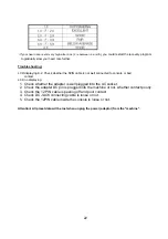
Selecting a Program to do training (PROGRAM)
-Press UP and DOWN keys to scan MANUAL
→
PROGRAM
USER PROGRAM
HRC
WATT.
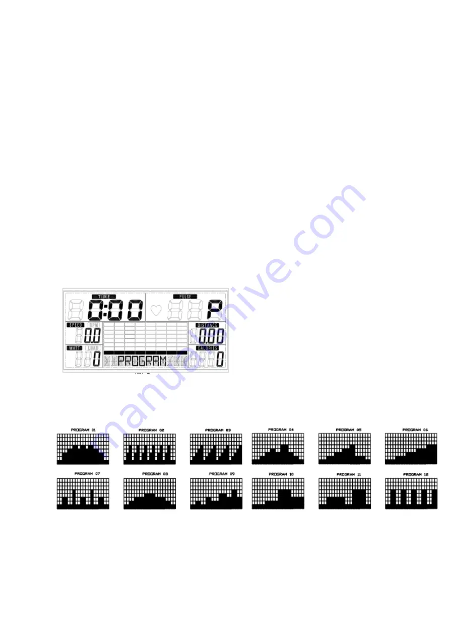
-Choose PROGRAM and press ENTER to confirm. The programs are preset with 12 profiles. Press UP
and DOWN to select one from the 12 preset profiles. Set the desired session value and confirm by
ENTER:
. Resistance level (1~16)
. TIME
-Press STATR/STOP to start workout.
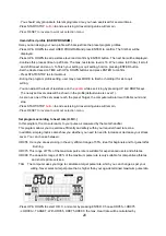
-You can adjust the level of resistance on the
pedals
while exercising by pressing UP and DOWN keys.
The newly set level value will be shown in the profile(default value is Level 1).
-Program profile & intensity:
Interval programs P2- P3- P7- P12
Increasing resistance level programs P6- P9- P11
Increasing and decreasing resistance level programs P1- P4- P5- P8 -P10
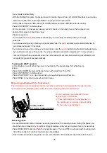
The stored training programs are designed especially to enhance aerobic base fitness.
. As a beginner you should start with those programs slowly and set a low
pedal
resistance.


