background image

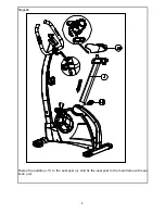
Stage#3 


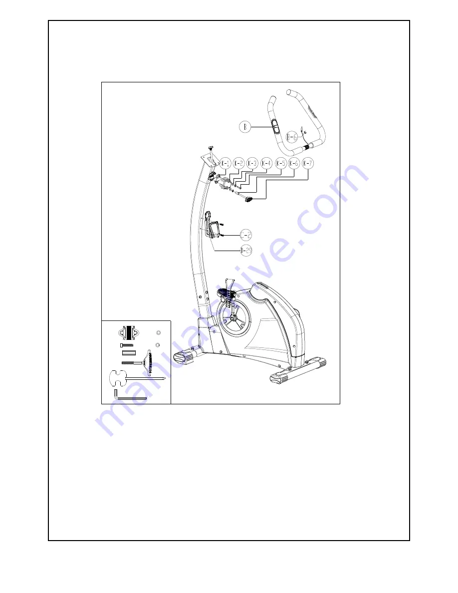
1.  Assemble the handlebar (B) to the bracket on the handlebar post with handlebar clamp 

(K-1), spring washer (K-3), washer (K-4) and screw (K-5). 

2.  Fix the spring washer (K-3), washer (K-4) and metal bush (K-6) into the handlebar clamp. 

Insert the plastic cover to the handlebar clamp. 

3.  Fix the T-knob (K-7) to the plastic cover. Adjust the handlebar with your desired angle. 

Fasten the T-knob. Tight the bottle holder (D-29) to the handlebar post with two screws 
(C-2). 


1*

1*

1*

1*

2*

2*


Summary of Contents for BT10.5 91006

Page 1: ...1 USER MANUAL BT10 5 91006...

Page 2: ...t for M8 Bolt 4 K 10 Carriage Bolt M8 P1 25 55MM 4 MM NO K 7 T shape knob M7 65L 1 K 5 Allen Bolt M7 P1 0 30MM 1 NO K 4 Spring Washer Screwdriver 1 Box Spanner 1 NO K 6 Bushing NO K 1 Metal cover 1 Al...

Page 3: ...1 Exploded view...

Page 4: ...1 Flat washer 8 19 2T 4PCS D 3 Screw M8 P1 25 16L 4PCS D 5 Bearing 6203 RS 2PCS D 6 Screw M4x10L 1PCS D 7 Sensor Box 1SET D 8 Flat washer 17 5x 25x0 3t 1PCS D 9 C type ring 17 1PCS D 10 Right front c...

Page 5: ...Lx5t 2PCS H 2 End cap Right for front Stabilizer 1PCS H 3 End cap Left for front Stabilizer 1PCS I Rear Stabilizer 1PCS I 1 End cap for rear Stabilizer 2PCS I 2 Adjustor 2PCS I 3 Nut 3 8 16x3t 2PCS J...

Page 6: ...Screw M7xP1 0x65L 1PCS K 8 Flat washer 8 19 2T 4PCS K 9 Nut M8 4PCS K 10 Screw M8xP1 25x55L 4PCS L Gear box set 1SET L 1 Screw M8 22L 1PCS L 2 Flat washer 8 19 2T 2PCS L 3 Screw M6xP1 0 16L 2PCS L 4 S...

Page 7: ...stabilizer I to the mainframe assembly Be noted the front stabilizer has transportation wheel Use carriage bolts K 10 curve washer K 8 and crown nut K 9 to fix the stabilizers tightly 2 Fix the right...

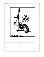
Page 8: ...6 Stage 2 1 Connect the upper and lower table together 2 Fix the handlebar post to the main frame with Screws D 3 and washer D 12 4...

Page 9: ...d screw K 5 2 Fix the spring washer K 3 washer K 4 and metal bush K 6 into the handlebar clamp Insert the plastic cover to the handlebar clamp 3 Fix the T knob K 7 to the plastic cover Adjust the hand...

Page 10: ...8 Stage 4 Fasten the saddle J 11 to the seat post J And fix the seat post to the main frame with seat knob J 2...

Page 11: ...puter A Place the computer to the computer mast and fasten with Screws A 1 Then the assembly is done Fix the handlebar to the console mast with attached hardware Have T knob J to go through bushing J...

Page 12: ...ay range 0 00 99 99 Setting range 0 00 99 90km CALORIES Display range 0 9999 Setting range 0 00 9990 PULSE Display range P 30 240 Setting range 0 30 240 WATT Display range 0 999 Setting range 10 350 S...

Page 13: ...0 User may hold on pressing MODE button for 2 seconds to quit profile setting 8 WATT The preset watt value 120 is flashing on screen in WATT setting mode User may use UP DOWN button to set target valu...

Page 14: ...conds NOTE 1 This computer require 9V 0 5mA adaptor 2 When user stop pedaling for 4 minutes computer will enter into power save mode all setting and exercise data will stored until user start exercise...

Reviews: