background image

HICKER B200

INSTRUCTION MANUAL / NOTICE DE MONTAGE / MONTAGEANLEITUNG / MANUAL DE MONTAJE / MANUAL DE MONTAGEM / MANUALE DI MONTAGGIO / MONTAGEHANDLEIDING / INSTRUKCJA MONTAŻU

EN

FR

DE

ES

PT

IT

NL

PL

STI-000044

EN

FR

DE

ES

PT

IT

NL

PL

The manual should be read prior to beginning installation and keep after

Le manuel doit être lu avant de commencer l’installation et conservé après

Das Handbuch sollte vor Beginn der Installation gelesen und nach der Installation aufbewahrt werden.

El manual debe ser leído antes de comenzar la instalación y mantenerlo después

O manual deve ser lido antes do início da instalação e mantido após

Il manuale deve essere letto prima di iniziare l’installazione e conservato dopo

De handleiding moet voor het begin van de installatie worden gelezen en na de installatie worden bewaard

Instrukcję należy przeczytać przed rozpoczęciem instalacji i zachować ją po

CAUTION / ATTENTION / ACHTUNG / ATENCIÓN / ATTENZIONE / AANDACHT / UWAGA

!

Summary of Contents for HICKER B200

Page 1: ...Handbuch sollte vor Beginn der Installation gelesen und nach der Installation aufbewahrt werden El manual debe ser leído antes de comenzar la instalación y mantenerlo después O manual deve ser lido antes do início da instalação e mantido após Il manuale deve essere letto prima di iniziare l installazione e conservato dopo De handleiding moet voor het begin van de installatie worden gelezen en na d...

Page 2: ...EN FR DE ES PT IT NL PL 3 25 47 69 91 113 135 157 Manual translated from English version using automatic translator In case of question please refer to english version ...

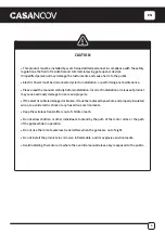
Page 3: ...roduct may cause seriously damage to users and property If the electric cable is damaged or broken it must be replaced by a whole and properly insulated wires to avoid electric shock or any hazardous environments Keep the wireless transmitters out of children reach Do not allow children or other individuals to stand by the path of the motor arms or the path of the gates while in operation Do not u...

Page 4: ...EN 4 Required Required Required Required Required Required Required Required Recommended Tools Required x2 x1 x1 x2 x2 x2 x2 x2 x4 x2 x2 x4 x2 x4 K L M N A B C D F G H I J E ...

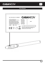
Page 5: ...EN 5 Serial Number ...

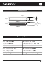
Page 6: ...en angle 110 degree Continue running time 5 minutes Dual Swing Gate automation s Gross weight 17 5KG Motor voltage 24VDC 60W Input power 220VAC 10 Rotational speed 300 RPM Arm s extended speed 2 4 cm s Arm s max travel 400 mm Max single leaf length 3 meters 620mm 400mm 897mm 64mm 65mm 75mm 80 mm Technical specifications ...

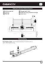
Page 7: ...e gate manually Manual unlocking Swing Gate automation Features Options Flash lamp optional Control box Photo cells 1 2 3 4 5 6 Swing gate opener motor Remove auto close and keep the central stop Remote control 6 1 2 3 3 4 4 2x1 5 mm 2 2x 0 5 mm 2 4x0 5 mm2 2x0 75 mm 2 2x1 5 mm 2 230V 2x1 5 mm 2 5 ...

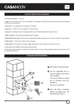
Page 8: ... to control the swing gate opener Battery Back Up DC 24V back up battery can be incorporated Optional Devices DC 24V Gate Lock photocell keypad photocell push button large size or small size control box The Gate Opener can be configured to allow smooth noiseless operation The Gate Opener can be configured to enable open condition as default or close condition as default depending on the placement ...

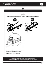
Page 9: ...RIP THE CABLE AND CAUSES ELECTRIC SHOCK WARNING Fixing motor on bracket Watch that the electric cable is in the proper position Power supply cable is in down position Manual unlocking slot on top position Endless screw arm is facing ground 2 1 3 1 3 5 6 4 4 6 OK KO Gx2 Mx2 ...

Page 10: ...EN 10 Installation of Extended End Motor Arms to Gates USE BUBBLE LEVEL K D mm ...

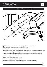
Page 11: ...rewing the worm screw bolt and screwing it onto the bracket and tighten it properly Please note that the bolts used to attach the front bracket to the gate are not supplied as the thickness of each gate is different Insert the locking pin and clamping washers Unlock the motor Open and close the gate manually to ensure correct operation A B C D Installation of Motor s Arms to Gates 84 10 2 A B C D ...

Page 12: ...EN 12 The distance between the edge of the post and the fixed hinge of the motor The distance between the door hinge and the centre line of the engine hinge A B INSTALLATION OPENING INWARDS ...

Page 13: ...EN 13 INSTALLATION OPENING OUTWARDS A B The distance between the edge of the post and the fixed hinge of the motor The distance between the door hinge and the centre line of the engine hinge ...

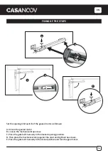
Page 14: ... A Unlock the geared motor B Loosen the mechanical stop screw C Place the gate leaf manually in the desired opening position D Then place the mechanical stop against the pivot and tighten the screws E Place the gate leaf manually in the closed position and lock the gear motor A B C D E ...

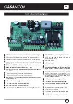
Page 15: ...is used for connecting flash light 24V DC lock output the NF terminal which used for connecting the electric lock COM is COMMON used for connecting the ground of lock 24V DC lock output the NA terminal which used for connecting the magnetic lock 24V DC alarm output 24V DC alarm output Motor1 terminal is used for connecting the motor 1 installed on the gate that opens later and close first This ter...

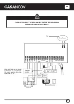
Page 16: ...CONNECTING THE CONTROL BOARD TO THE 230V AND TO ACCESSORIES 1 2 3 4 5 6 7 8 9 10 11 12 13 14 15 16 17 18 19 21 20 22 25 26 2 side and 1 side are for connect open device such as push but ton wired keypad camera video GSM controller etc ...

Page 17: ...EN 17 IR OUT COM COM 12V 05 COM 06 IR 07 12V 19 20 21 22 BLUE BROWN BROWN BLUE 19 20 21 22 ...

Page 18: ...l display will self check from 00 99 with buzzer sound If indicator LED light on buzzer stop sound it means the system is normal Basic operation method Press and hold the FUN button until the digital display shows PO Now you enter the menu setting You could through adjust the INC DEC to increase or decrease the serial number or numerical value After data adjust well then press FUN to store the dat...

Page 19: ...ng stall force adjustment 0 20Level 10th Level M2 HI OVER LOAD P5 To set the high speed running time 0 33s 5s HI SPEED P6 To set the auto close time after swipe card 0 99s 10s CARD CLOSE AUTO CLOSE P7 To set the Interval time on opening the door 0 10s 0 close OPEN DELAY P8 To set the Interval time on closing the door 0 10s 0 close CLOSE DELAY P9 To set auto close time 0 99s 0 close AUTO CLOSE PA T...

Page 20: ...adjustment finished factory set 6 level 2d When digital display indicate P4 the gate ope ner is on Motor 2 high speed running stall force ad justment There is 0 20 levels for optional Each time you press and release the INC button the figure increase by 1 each time you press and release the DEC button the figure decrease by 1 Press the FUN button to store the data when the stall force level chosen...

Page 21: ...age output after the gate total close 30s other time with voltage output 3 means the alarm on bistabillity model and the lamp would only flash when gate running Each time you press and release the INC button the figure increase by 1 each time you press and release the DEC button the figure decrease by 1 Press the FUN button to store the data when the auto close time chosen then the lamp alarm outp...

Page 22: ...al operation 2 Please be sure the power is off before connecting the product is produced without fuse Flash lamp assembly Power input connect to PCB board terminal 12 for and 13 for Working power 12V 265V DC AC 2 SW1 switch It s the switch for switching LED in flickering or lighting When SW1 at connecting LED will flicker after power on When SW1 at disconnecting LED will light after power on Pleas...

Page 23: ...ect terminal 5 to the IR of photocell RX Terminal is supplying power for external device So connect terminal 7 to the of photocell RX and TX Connect terminal to 5 the of photocell RX and TX Photocells 1 2 3 4 5 6 7 8 9 10 11 12 13 14 15 16 17 18 19 21 20 22 ...

Page 24: ...such time as the system in wich they are incorporated is declared conform to European directive Any modification made on the machine without our prior acceptance is making this declaration not va lid Main technical caracteristics Motor voltage 24VDC 60W Input power 220VAC 10 Rotational speed 300 RPM Arm s extended speed 2 4 cm s Arm s max travel 400 mm Continue running time 5 minutes Max single ve...

Page 25: ...it peut causer de sérieux dommages aux utilisateurs et aux biens Si le câble électrique est endommagé ou cassé il doit être remplacé par un ensemble de fils correctement isolés afin d éviter tout choc électrique ou tout environnement dangereux Gardez les émetteurs sans fil hors de portée des enfants Ne laissez pas les enfants ou d autres personnes se tenir sur le chemin des bras moteurs ou sur le ...

Page 26: ...FR 26 Obligatoire Obligatoire Obligatoire Obligatoire Obligatoire Obligatoire Obligatoire Obligatoire Recommandé Outils nécessaires x2 x1 x1 x2 x2 x2 x2 x2 x4 x2 x2 x4 x2 x4 K L M N A B C D F G H I J E ...

Page 27: ...FR 27 Numéro de série ...

Page 28: ...degrés Durée de fonctionnement en continu 5 minutes Poids brut de l automatisation des portes à double battant 17 5KG Tension du moteur 24VDC 60W Puissance d entrée 220VAC 10 Vitesse de rotation 300 RPM Vitesse d extension du bras 2 4 cm s Course maximale du bras 400 mm Longueur maximale d un évent simple 3 mètres 620mm 400mm 897mm 64mm 65mm 75mm 80 mm Spécifications techniques ...

Page 29: ...riques 1 2 3 4 5 6 Moteur de l ouvre porte à battants Enlever la fermeture automatique et garder l arrêt Télécommande Ouvrez le portail manuellement Utilisez la clé de commande manuelle pour débrayer l embrayage afin d ouvrir ou de fermer le portail manuellement 6 1 2 3 3 4 4 2x1 5 mm 2 2x 0 5 mm 2 4x0 5 mm2 2x0 75 mm 2 2x1 5 mm 2 230V 2x1 5 mm 2 5 ...

Page 30: ...rrage en douceur Fermeture automatique Le système d ouverture de porte est équipé d une fonction de fermeture automatique avec un délai de fermeture réglable Porte simple ou double Il est possible d ouvrir une porte à simple ou double battant Plusieurs émetteurs à distance Le contrôleur peut facilement accueillir plusieurs télécommandes supplémentaires uniques pour contrôler l ouvre porte à battan...

Page 31: ...UER UN CHOC ÉLECTRIQUE FIXATION DU MOTEUR SUR LE SUPPORT Veillez à ce que le câble électrique soit dans la bonne position Le câble d alimentation électrique est en position basse La fente de déverrouillage manuel est en position haute Le bras à vis sans fin est tourné vers le sol 2 1 3 1 3 5 6 4 4 6 OK KO Gx2 Mx2 ...

Page 32: ...FR 32 Installation des bras motorisés sur le portail K D UTILISER UN NIVEAU mm ...

Page 33: ...mité sur le support du portail en devissant le boulon de la vis sans fin et en le vissant sur la patte de fixation et serrez les correctement Veuillez noter que les boulons utilisés pour fixer le support avant à la porte ne sont pas fournis car l épaisseur de chaque porte est différente Insérer la goupille de verrouillage et les rondelles de serrage Dévérouiller le moteur Ouvrez et fermez le porta...

Page 34: ... 34 La distance entre le bord du poteau et la charnière fixe du moteur La distance entre la charnière de la porte et la ligne centrale de la charnière du moteur A B INSTALLATION OUVERTURE VERS L INTERIEUR ...

Page 35: ... 35 INSTALLATION OUVERTURE VERS L EXTÉRIEUR La distance entre le bord du poteau et la charnière fixe du moteur La distance entre la charnière de la porte et la ligne centrale de la charnière du moteur A B ...

Page 36: ...oréducteur B Desserrez la vis de l arrêt mécanique C Placez manuellement le vantail du portail dans la position désirée en ouverture D Placez ensuite l arrêt mécanique en butée contre le pivot et bloquez les vis E Placez manuellement le vantail du portail dans la position de fermeture puis bloquez le motoréducteur A B C D E ...

Page 37: ...e 24V DC la borne NF qui est utilisée pour connecter la serrure électrique COM est COMMON utilisé pour connecter la masse de la serrure Sortie de serrure 24V DC la borne NA utilisée pour connecter la serrure magnétique Sortie d alarme 24V DC Sortie d alarme 24V DC La borne du moteur 1 est utilisée pour connecter le moteur 1 installé sur le portail qui s ouvre plus tard et se ferme en premier Cette...

Page 38: ...ABLEAU DE COMMANDE AU 230V ET AUX ACCESSOIRES 1 2 3 4 5 6 7 8 9 10 11 12 13 14 15 16 17 18 19 21 20 22 25 26 2 côtés et 1 côté sont pour les appareils ouverts tels que les boutons poussoirs les claviers câblés les caméras vidéo les contrôleurs GSM etc ...

Page 39: ...FR 39 IR OUT COM COM 12V 05 COM 06 IR 07 12V 19 20 21 22 19 20 21 22 BLEU MARRON BLEU MARRON ...

Page 40: ...succès Après la mise sous tension l affichage numérique s auto vérifie de 00 à 99 avec le son du buzzer Si le voyant LED s allume le buzzer arrête le son cela signifie que le système est normal Mode de fonctionnement de base Appuyez et maintenez le bouton FUN enfoncé jusqu à ce que l affichage numérique indique PO Vous accédez alors au réglage du menu Vous pouvez régler le INC DEC pour augmenter o...

Page 41: ...ctionnement Niveau 0 20 10e niveau M2 HI OVER LOAD P5 Pour régler la durée de fonctionnement à grande vitesse 0 33s 5s HI SPEED P6 Pour régler le temps de fermeture automatique après le passage de la carte 0 99s 10s CARD CLOSE AUTO CLOSE P7 Pour fixer le délai d ouverture de la porte 0 10s 0 Fermer OPEN DELAY P8 Pour fixer l intervalle de temps de fermeture de la porte 0 10s 0 Fermer CLOSE DELAY P...

Page 42: ...r 2 à faible vitesse de fonctionnement est réglée niveau 6 réglé en usine 2d Lorsquel affichagenumériqueindiqueP4 l ouvre bar rière est sur le réglage de la force de décrochage à grande vitesse du moteur 2 Il y a de 0 à 20 niveaux pour l option Chaque fois que vous appuyez et relâchez le bouton INC le chiffre augmente de 1 chaque fois que vous appuyez et relâchez le bouton DEC le chiffre diminue d...

Page 43: ...porte est en marche 2 signifie que l alarme est sur le modèle bistabillité et que la lampe sans tension de sortie après la fermeture totale de la porte pendant 30 secondes 3 signifie que l alarme est sur le modèle de bistabillité et que la lampe ne clignote que lorsque la porte est en marche Chaque fois que vous appuyez et relâchez le bouton INC le chiffre augmente de 1 chaque fois que vous appuye...

Page 44: ...er que l alimentation électrique est coupée avant de brancher le produit celui ci étant fabriqué sans fusible Assemblage de la lampe flash Entrée d alimentation à connecter à la borne 12 du circuit imprimé pour le et à la borne 13 pour le Puissance de fonctionnement 12V 265V DC AC 2 commutateur SW1 C est l interrupteur qui permet d allumer ou de faire clignoter les LED Lorsque le SW1 est connecté ...

Page 45: ...électrique RX La borne fournit l alimentation pour le dispositif externe Donc connectez la borne 7 au de la cellule photoélectrique RX et TX Connectez le terminal 5 au de la cellule photoélectrique RX et TX Cellules photoélectriques 1 2 3 4 5 6 7 8 9 10 11 12 13 14 15 16 17 18 19 21 20 22 Cellules photoélectriques ...

Page 46: ...é conforme à la directive européenne Toute modification apportée à la machine sans notre accord préalable rend cette déclaration non valable Principales caractéristiques techniques Tension du moteur 24V 60W Puissance d entrée 220VAC 10 Vitesse de rotation 300 RPM Vitesse d extension du bras 2 4 cm s Course maximale du bras 400 mm Durée de fonctionnement continu 5 minutes Longueur maximale d un ven...

Page 47: ...ann zu ernsthaften Schäden an Benutzern und Eigentum führen Wenn das elektrische Kabel beschädigt oder gebrochen ist muss es durch ein ganzes und ordnungsgemäß isoliertes Kabel ersetzt werden um einen elektrischen Schlag oder gefährliche Umgebungen zu vermeiden Bewahren Sie die Funksender außerhalb der Reichweite von Kindern auf Erlauben Sie Kindern oder anderen Personen nicht während des Betriebs...

Page 48: ...Erforderlich Erforderlich Erforderlich Erforderlich Erforderlich Erforderlich Erforderlich Erforderlich Empfohlen Erforderliche Werkzeuge x2 x1 x1 x2 x2 x2 x2 x2 x4 x2 x2 x4 x2 x4 K L M N A B C D F G H I J E ...

Page 49: ...DE 49 Seriennummer ...

Page 50: ...uierliche Laufzeit 5 Minuten Bruttogewicht der Automatisierung des Doppelschwenktors 17 5KG Motorspannung 24VDC 60W Eingangsleistung 220VAC 10 Umdrehungsgeschwindigkeit 300 RPM Geschwindigkeit bei ausgefahrenem Arm 2 4 cm s Maximaler Verfahrweg des Arms 400 mm Maximale Länge einer einzelnen Entlüftung 3 Meter 620mm 400mm 897mm 64mm 65mm 75mm 80 mm Technische Spezifikationen ...

Page 51: ...en 1 2 3 4 5 6 Motor des Drehtoröffners Autozufahrt entfernen und den Zentralanschlag beibehalten Fernsteuerung Öffnen Sie das Tor von Hand Zum manuellen Öffnen oder Schließen des Tores die Kupplung mit dem Handbetätigungsschlüssel lösen 6 1 2 3 3 4 4 2x1 5 mm 2 2x 0 5 mm 2 4x0 5 mm2 2x0 75 mm 2 2x1 5 mm 2 230V 2x1 5 mm 2 5 ...

Page 52: ...er Toröffner ist mit einer Sanftanlauffunktion ausgestattet Automatisches Schließen Das Toröffnersystem ist mit einer automatischen Schließfunktion mit einstellbarer Schließzeitverzögerung ausgestattet Einzel oder Doppel Tor Es kann entweder ein Einzel oder ein Doppelschwenktor geöffnet werden Mehrere Fernsteuersender Die Steuerung kann problemlos mehrere einzigartige Zusatzfernbedienungen zur Ste...

Page 53: ...LEKTRISCHEN SCHLAG VERURSACHEN MOTOR AUF KONSOLE BEFESTIGEN Achten Sie darauf dass sich das Elektrokabel in der richtigen Position befindet Stromversorgungskabel befindet sich in der unteren Position Manueller Entriegelungsschlitz in oberer Position Der Arm der Endlosschraube zeigt zum Boden 2 1 3 1 3 5 6 4 4 6 OK KO Gx2 Mx2 ...

Page 54: ...DE 54 Installation von verlängerten Endmotorarmen an Toren K D VERWENDUNG EINER WASSERWAAGE mm ...

Page 55: ...terung auf die Torhalterung indem Sie die Schneckenschraube herausdrehen und auf die Halterung schrauben und richtig festziehen Bitte beachten Sie dass die Schrauben zur Befestigung der vorderen Halterung am Tor nicht mitgeliefert werden da die Dicke jedes Tores unterschiedlich ist Setzen Sie den Sicherungsstift und die Klemmscheiben ein Entriegeln Sie den Motor Öffnen und schließen Sie das Tor ma...

Page 56: ...DE 56 Der Abstand zwischen der Kante des Pfostens und dem festen Scharnier des Motors Der Abstand zwischen dem Türscharnier und die Mittellinie des Motorscharniers A B INSTALLATION NACH INNEN ÖFFNEND ...

Page 57: ...DE 57 INSTALLATION ÖFFNUNG NACH AUSSEN A B Der Abstand zwischen der Kante des Pfostens und dem festen Scharnier des Motors Der Abstand zwischen dem Türscharnier und die Mittellinie des Motorscharniers ...

Page 58: ...motor B Lösen Sie die mechanische Anschlagschraube C Bringen Sie den Torflügel manuell in die gewünschte Öffnungsposition D Setzen Sie dann den mechanischen Anschlag gegen den Drehpunkt und ziehen Sie die Schrauben fest E Stellen Sie den Torflügel manuell in die geschlossene Position und arretieren Sie den Getriebemotor A B C D E ...

Page 59: ... NF Klemme die für den Anschluss des Elektroschlosses verwendet wird COM ist COMMON der für den Anschluss der Masse des Schlosses verwendet wird 24V DC Schlossausgang der NA Anschluss der für den Anschluss des Magnetschlosses verwendet wird 24V DC Alarmausgang 24V DC Alarmausgang Die Klemme Motor1 wird für den Anschluss des Motors 1 verwendet der auf dem Tor installiert ist das später öffnet und z...

Page 60: ...E DIE STEUERPLATINE AN DIE 230V UND AN ZUBEHÖR ANSCHLIESSEN 1 2 3 4 5 6 7 8 9 10 11 12 13 14 15 16 17 18 19 21 20 22 25 26 2 Seiten und 1 Seite sind für conncet offenes Gerät wie z B Druckknopf verdrahtete Tastatur Kamera Video GSM Controller usw ...

Page 61: ...DE 61 IR OUT COM COM 12V 05 COM 06 IR 07 12V 19 20 21 22 BLAU BRAUN BRAUN BLAU 19 20 21 22 ...

Page 62: ...gitalanzeige einen Selbsttest von 00 99 mit Summton durch Wenn die LED Anzeige aufleuchtet und der Summer ertönt bedeutet dies dass das System normal ist Grundlegende Betriebsmethode Halten Sie die FUN Taste gedrückt bis die Digitalanzeige PO anzeigt Jetzt gelangen Sie in die Menüeinstellung Sie können die INC DEC Taste drücken um die Seriennummer oder den numerischen Wert zu erhöhen oder zu verri...

Page 63: ...ng der Laufzeit bei hoher Geschwindigkeit 0 33s 5s HI SPEED P6 So stellen Sie die Zeit für das automatische Schließen nach dem Durchziehen der Karte ein 0 99s 10s CARD CLOSE AUTO CLOSE P7 So stellen Sie die Intervallzeit beim Öffnen der Tür ein 0 10s 0 schließen OPEN DELAY P8 So stellen Sie die Intervallzeit beim Schließen der Tür ein 0 10s 0 schließen CLOSE DELAY P9 Zum Einstellen der automatisch...

Page 64: ...jedem Drücken und Loslassen der INC Taste erhöht sich die Zahl um 1 bei jedem Drücken und Loslassen der DEC Taste verringert sich die Zahl um 1 Drücken Sie die FUN Taste um die Daten zu speichern wenn die gewählte Überziehkraftstufe und dann die Einstellung der Überziehkraft von Motor 2 für den Hochgeschwindigkeits lauf beendet ist Werkseinstellung 10 Stufen 3 Einstellen der Hochgeschwindigkeits L...

Page 65: ...Loslassen der INC Taste erhöht sich der Wert um 1 bei jedem Drücken und Loslassen der DEC Taste verringert sich der Wert um 1 Drücken Sie die FUN Taste um die Daten zu speichern wenn die automatische Schließzeit gewählt wurde und die Einstellung der Lampen Alarmausgangssteuerung abgeschlossen ist Werkseinstellung 0 8 Zum Einstellen der Sperrzeit Wenn die Digitalanzeige Pb anzeigt befindet sich der...

Page 66: ... dem Anschließen dass der Strom abgeschaltet ist das Produkt ist ohne Sicherung hergestellt Blitzlampen Baugruppe Leistungseingang an Leiterplattenklemme 12 für und 13 für anschließen Arbeitsleistung 12V 265V DC AC 2 Schalter SW1 Es ist der Schalter zum Schalten von LED bei Flackern oder Beleuchtung Wenn SW1 angeschlossen ist flackert die LED nach dem Einschalten Wenn SW1 die Verbindung trennt leu...

Page 67: ...schluss der Fotozelle RX anschließen Der Anschluss liefert Strom für ein externes Gerät Verbinden Sie also Klemme 7 mit dem der Fotozelle RX und TX Verbinden Sie Klemme 5 mit dem der Fotozelle RX und TX Fotozellen 1 2 3 4 5 6 7 8 9 10 11 12 13 14 15 16 17 18 19 21 20 22 Fotozellen ...

Page 68: ...r europäischen Richtlinie erklärt wird Jede Änderung an der Maschine die ohne unsere vorherige Zustimmung vorgenommen wird macht diese Erklärung ungültig Technische Hauptmerkmale Motorspannung 24VDC 60W Eingangsleistung 220VAC 10 Umdrehungsgeschwindigkeit 300 RPM Geschwindigkeit des ausgestreckten Armes 2 4 cm s Maximaler Verfahrweg des Arms 400 mm Fortsetzung der Laufzeit 5 Minuten Maximale Länge...

Page 69: ...del producto puede causar graves daños a los usuarios y a la propiedad Sielcableeléctricoestádañadooroto debeserreemplazadoporuncableenteroydebidamente aislado para evitar descargas eléctricas o entornos peligrosos Mantenga los transmisores inalámbricos fuera del alcance de los niños No permita que los niños u otras personas se paren junto a la trayectoria de los brazos motores o la trayectoria de...

Page 70: ...ES 70 Requerido Requerido Requerido Requerido Requerido Requerido Requerido Requerido Recomendado Herramientas necesarias x2 x1 x1 x2 x2 x2 x2 x2 x4 x2 x2 x4 x2 x4 K L M N A B C D F G H I J E ...

Page 71: ...ES 71 Número de serie ...

Page 72: ...iempo de funcionamiento continuo 5 minutos Peso bruto de la automatización de la puerta giratoria doble 17 5KG Voltaje del motor 24VDC 60W Potencia de entrada 220VAC 10 Velocidad de rotación 300 RPM Velocidad del brazo extendido 2 4 cm s Recorrido máximo del brazo 400 mm Longitud máxima de la ventilación 3 metros 620mm 400mm 897mm 64mm 65mm 75mm 80 mm Especificaciones técnicas ...

Page 73: ... 1 2 3 4 5 6 Motor de apertura de la puerta giratoria Quitar el cierre automático y mantener el tope central Mando a distancia Abrir el portón manualmente Utilice la llave de anulación manual para liberar el embrague para abrir o cerrar el portón manualmente 6 1 2 3 3 4 4 2x1 5 mm 2 2x 0 5 mm 2 4x0 5 mm2 2x0 75 mm 2 2x1 5 mm 2 230V 2x1 5 mm 2 5 ...

Page 74: ...stema de Abridor de Puerta está equipado con la función de cierre automático con un tiempo de retardo de cierre ajustable Puerta simple o doble Se puede abrir una puerta giratoria simple o doble Múltiples transmisores remotos El controlador puede acomodar fácilmente varios mandos adicionales únicos para controlar el abridor de la puerta abatible Múltiples transmisores remotos El controlador puede ...

Page 75: ...CARGA ELÉCTRICA FIJANDO EL MOTOR EN EL SOPORTE Cuidado con que el cable eléctrico esté en la posición correcta El cable de la fuente de alimentación está en posición baja Ranura de desbloqueo manual en la posición superior El brazo de tornillo sin fin está orientado hacia el suelo 2 1 3 1 3 5 6 4 4 6 OK KO Gx2 Mx2 ...

Page 76: ...ES 76 Instalación de brazos de motor de extremo extendido a las puertas K D USANDO UN NIVEL DE BURBUJÀ mm ...

Page 77: ...l soporte del motor final en el soporte de la puerta destornillando el tornillo sin fin y atornillándolo en el soporte y ajústelo correctamente Tenga en cuenta que los pernos utilizados para fijar el soporte frontal a la puerta no se suministran ya que el grosor de cada puerta es diferente Inserte el pasador de bloqueo y las arandelas de sujeción Desbloquea el motor Abra y cierre la puerta manualm...

Page 78: ...ES 78 La distancia entre el borde del poste y la bisagra fija del motor La distancia entre la bisagra de la puerta y la línea central de la bisagra del motor A B INSTALACIÓN APERTURA HACIA EL INTERIOR ...

Page 79: ...ES 79 INSTALACIÓN APERTURA HACIA EL EXTERIOR A B La distancia entre el borde del poste y la bisagra fija del motor La distancia entre la bisagra de la puerta y la línea central de la bisagra del motor ...

Page 80: ...loquee el motorreductor B Afloje el tornillo de tope mecánico C Coloque la hoja de la puerta manualmente en la posición de apertura deseada D A continuación coloque el tope mecánico contra el pivote y apriete los tornillos E Coloque la hoja de la puerta manualmente en posición cerrada y bloquee el motorreductor A B C D E ...

Page 81: ...ámpara de 24V DC se usa para conectar la luz de flash Salida de la cerradura de 24V DC el terminal NF que se utiliza para conectar la cerradura eléctrica COM es COMÚN usado para conectar la tierra de la cerradura Salida de la cerradura de 24 V CC el terminal NA que se utilizó para conectar la cerradura magnética Salida de alarma de 24 V CC Salida de alarma de 24 V CC El terminal del motor 1 se uti...

Page 82: ...TABLERO DE CONTROL A LOS 230V Y A LOS ACCESORIOS 1 2 3 4 5 6 7 8 9 10 11 12 13 14 15 16 17 18 19 21 20 22 25 26 2 lados y 1 lado son para el dispo sitivo abierto de conncet como el pulsador el teclado alámbrico la cámara de vídeo el controlador GSM etc ...

Page 83: ...ES 83 IR OUT COM COM 12V 05 COM 06 IR 07 12V 19 20 21 22 AZUL MARRÓN MARRÓN AZUL 19 20 21 22 ...

Page 84: ...n éxito Después del encendido la pantalla digital se autocomprobará de 00 99 con el sonido de un zumbador Si el indicador LED se enciende y el zumbador deja de sonar significa que el sistema es normal Método de funcionamiento básico Mantenga pulsado el botón FUN hasta que la pantalla digital muestre PO Ahora entrará en el ajuste del menú Puede ajustar el INC DEC para aumentar o disminuir el número...

Page 85: ...I OVER LOAD P5 Para ajustar el tiempo de funcionamiento de alta velocidad 0 33s 5s HI SPEED P6 Para establecer el tiempo de cierre automático después de pasar la tarjeta 0 99s 10s CARD CLOSE AUTO CLOSE P7 Para establecer el tiempo de intervalo de apertura de la puerta 0 10s 0 cerrar OPEN DELAY P8 Para establecer el tiempo de intervalo al cerrar la puerta 0 10s 0 cerrar CLOSE DELAY P9 Para establec...

Page 86: ...s de 0 20 para el opcio nal Cada vez que se presiona y suelta el botón INC la cifra aumenta en 1 cada vez que se presiona y se suelta el botón DEC la cifra disminuye en 1 Presione el botón FUN para almacenar los datos cuando el nivel de fuerza de pérdida elegido y luego la fuerza de pérdida del ajuste de la fuerza de pérdida de la marcha de alta velocidad del Motor 2 terminó nivel ajustado de fábr...

Page 87: ...os 3 significa que la alarma está en el modelo biestable y la lámpara sólo parpadeará cuando la puerta esté funcionando Cada vez que se presiona y suelta el botón INC la cifra aumenta en 1 cada vez que se presiona y se suelta el botón DEC la cifra disminuye en 1 Presione el botón FUN para almacenar los datos cuando se elija el tiempo de cierre automático y luego el ajuste de control de la salida d...

Page 88: ... asegúrese de que la alimentación esté apagada antes de conectarla el producto se produce sin fusible Ensamblaje de la lámpara de flash La entrada de energía se conecta al terminal 12 de la placa de circuito impreso para y 13 para Potencia de trabajo 12V 265V DC AC 2 interruptor SW1 Es el interruptor para cambiar el LED en parpadeo o iluminación Cuando SW1 se conecta el LED parpadeará después de e...

Page 89: ...l IR de la fotocélula RX El terminal está suministrando energía para el dispositivo externo Así que conecta el terminal 7 al de la fotocélula RX y TX Conecte el terminal 5 al de la fotocélula RX y TX Fotocélulas 1 2 3 4 5 6 7 8 9 10 11 12 13 14 15 16 17 18 19 21 20 22 Fotocélulas ...

Page 90: ...a declarado conforme a la directiva europea Cualquier modificación realizada en la máquina sin nuestra previa aceptación hace que esta declaración no sea válida Principales características técnicas Voltaje del motor 24VDC 60W Potencia de entrada 220VAC 10 Velocidad de rotación 300 RPM Velocidad del brazo extendido 2 4 cm s Recorrido máximo del brazo 400 mm Tiempo de funcionamiento 5 minutos Longit...

Page 91: ... pode causar danos graves aos utilizadores e à propriedade Se o cabo eléctrico estiver danificado ou partido deve ser substituído por fios inteiros e devidamente isolados para evitar choques eléctricos ou quaisquer ambientes perigosos Manter os transmissores sem fios fora do alcance das crianças Não permitir que crianças ou outros indivíduos fiquem ao lado do caminho dos braços do motor ou do cami...

Page 92: ...92 Obrigatório Obrigatório Obrigatório Obrigatório Obrigatório Obrigatório Obrigatório Obrigatório Recomendado Ferramentas Necessárias x2 x1 x1 x2 x2 x2 x2 x2 x4 x2 x2 x4 x2 x4 K L M N A B C D F G H I J E ...

Page 93: ...PT 93 Número de série ...

Page 94: ...graus Tempo de funcionamento contínuo 5 Minutos Peso bruto da automatização da Dual Swing Gate 17 5KG Tensão do motor 24VDC 60W Potência de entrada 220VAC 10 Velocidade rotacional 300 RPM Velocidade extendida do braço 2 4 cm s Curso máximo do braço 400 mm Comprimento máximo de um respiradouro 3 Metros 620mm 400mm 897mm 64mm 65mm 75mm 80 mm Especificações técnicas ...

Page 95: ...5 6 Motor de apertura de la puerta giratoria Quitar el cierre automático y mantener el tope central Mando a distancia Abrir a porta manualmente Utilize a chave de desbloqueio manual para libertar a embraiagem para abrir ou fechar a porta manualmente 6 1 2 3 3 4 4 2x1 5 mm 2 2x 0 5 mm 2 4x0 5 mm2 2x0 75 mm 2 2x1 5 mm 2 230V 2x1 5 mm 2 5 ...

Page 96: ...suave Fecho Automático O Sistema de Abertura de Portas está equipado com a função de Fecho Automático com temporização de fecho ajustável Portão simples ou duplo Pode ser aberta uma ou duas portas de batente Transmissores Remotos Múltiplos O Controlador pode facilmente acomodar vários telecomandos extra únicos para controlar o comando de abertura da porta basculante Back Up da bateria Bateria de r...

Page 97: ...AUSAR UM CHOQUE ELÉCTRICO FIXAÇÃO DO MOTOR NO SUPORTE Cuidado para que o cabo eléctrico fique na posição correcta O cabo de alimentação está na posição inferior Ranhura de desbloqueio manual na posição superior O braço de parafuso sem fim está virado para o chão 2 1 3 1 3 5 6 4 4 6 OK KO Gx2 Mx2 ...

Page 98: ...PT 98 Instalação de Braços de Motor Extendidos a Portões K D UTILIZAÇÃO DE UM NÍVEL DE BOLHA mm ...

Page 99: ...rte final do motor no suporte da porta desaparafusando o parafuso sem fim e aparafusando o no suporte e apertando o correctamente Note que os parafusos utilizados para fixar o suporte frontal à porta não são fornecidos uma vez que a espessura de cada porta é diferente Inserir o pino de bloqueio e as anilhas de aperto Desbloquear o motor Abrir e fechar o portão manualmente para assegurar um funcion...

Page 100: ...PT 100 A distância entre a borda do poste e a dobradiça fixa do motor A distância entre a dobradiça da porta e a linha central da dobradiça do motor A B INSTALAÇÃO ABERTURA PARA DENTRO ...

Page 101: ...PT 101 INSTALAÇÃO ABERTURA PARA O EXTERIOR A B A distância entre a borda do poste e a dobradiça fixa do motor A distância entre a dobradiça da porta e a linha central da dobradiça do motor ...

Page 102: ...quear o moto redutor B Desaperte o parafuso de paragem mecânica C Colocar a folha do portão manualmente na posição de abertura desejada D Em seguida colocar o batente mecânico contra o pino e apertar os parafusos E Colocar a folha do portão manualmente na posição fechada e bloquear o motor da engrenagem A B C D E ...

Page 103: ... de 24V DC é utilizada para ligar a luz intermitente Saída da fechadura de 24V DC o terminal NF utilizado para ligar a fechadura eléctrica COM é COMUM utilizado para ligar a terra da eclusa Saída da eclusa de 24V DC o terminal NA utilizado para a ligação da fechadura magnética Saída de alarme de 24V DC Saída de alarme de 24V DC O terminal Motor1 é utilizado para ligar o motor 1 instalado na porta ...

Page 104: ...IGAR A PLACA DE COMANDO AOS 230V E AOS ACESSÓRIOS 1 2 3 4 5 6 7 8 9 10 11 12 13 14 15 16 17 18 19 21 20 22 25 26 2 lados e 1 lado são para dispo sitivo aberto de conncet como botão de pressão teclado com fio vídeo da câmara controlador GSM etc ...

Page 105: ...PT 105 IR OUT COM COM 12V 05 COM 06 IR 07 12V 19 20 21 22 AZUL CASTANHO CASTANHO AZUL 19 20 21 22 ...

Page 106: ...pois de ligado o visor digital irá auto verificar a partir de 00 99 com som de campainha Se a luz indicadora LED acender o som do buzzer pára significa que o sistema está normal Método básico de funcionamento Mantenha pressionado o botão FUN até que o mostrador digital mostre PO Agora você entra na configuração do menu Pode ajustar o INC DEC para aumentar ou diminuir o número de série ou o valor n...

Page 107: ...el 10º Nível M2 HI OVER LOAD P5 Para ajustar o tempo de funcionamento a alta velocidade 0 33s 5s HI SPEED P6 Para ajustar o tempo de fecho automático após a passagem do cartão 0 99s 10s CARD CLOSE AUTO CLOSE P7 Para definir o tempo de Intervalo ao abrir a porta 0 10s 0 fechar OPEN DELAY P8 Para definir o tempo de Intervalo ao fechar a porta 0 10s 0 fechar CLOSE DELAY P9 Para definir a hora de fech...

Page 108: ...ção escolhido depois o ajuste da força de paralisação do Motor 2 de alta velocidade terminou nível 10 ajustado de fábrica 3 Para definir o tempo de corrida de alta velocidade Quando o visor digital indica P5 o abridor de porta está no ajuste do tempo de funcionamento a alta velocidade Há 0 33s para opcional 0s significa que sem alta veloci dade de funcionamento o abridor de porta continuaria a fun...

Page 109: ...rima o botão FUN para guardar os dados quando o tempo de fecho automático escolhido depois a definição do controlo de saída da lâmpada alarme terminou conjunto fac tório 0 8 Para definir o tempo de bloqueio Quando o visor digital indica Pb o comando de abertura da porta está na definição do tempo de tranca O tempo de controlo da fechadura significa o tempo em que se pode controlar a fechadura Exis...

Page 110: ... certifique se de que a energia está desligada antes de ligar o produto é produzido sem fusível Montagem da lâmpada flash Entrada de alimentação ligar ao terminal 12 da placa PCB para e 13 para Potência de trabalho 12V 265V DC AC 2 SW1 interruptor É o interruptor para comutar o LED em cintilação ou iluminação Quando o SW1 se liga o LED cintila depois de ligado Quando SW1 ao desligar o LED acenderá...

Page 111: ...al 5 ao IR da fotocélula RX O terminal está a fornecer energia para o dispositivo externo Assim ligue o terminal 7 ao da fotocélula RX e TX Ligue o terminal 5 ao da fotocélula RX e TX Fotocélulas 1 2 3 4 5 6 7 8 9 10 11 12 13 14 15 16 17 18 19 21 20 22 Fotocélulas ...

Page 112: ...eclarado conforme à directiva europeia Qualquer modificação efectuada na máquina sem a nossa aceitação prévia torna esta declaração inválida Principais características técnicas Tensão do motor 24VDC 60W Potência de entrada 220VAC 10 Velocidade de rotação 300 RPM Velocidade do braço estendido 2 4 cm s Curso máximo do braço 400 mm Tempo de funcionamento 5 minutos Comprimento máximo de ventilação úni...

Page 113: ...n uso improprio del prodotto può causare gravi danni agli utenti e alle cose Se il cavo elettrico è danneggiato o rotto deve essere sostituito con un cavo intero e correttamente isolato per evitare scosse elettriche o ambienti pericolosi Tenere i trasmettitori wireless fuori dalla portata dei bambini Non permettere ai bambini o ad altri individui di stare vicino al percorso delle braccia del motor...

Page 114: ... Obbligatorio Obbligatorio Obbligatorio Obbligatorio Obbligatorio Obbligatorio Obbligatorio Obbligatorio Raccomandato Strumenti richiesti x2 x1 x1 x2 x2 x2 x2 x2 x4 x2 x2 x4 x2 x4 K L M N A B C D F G H I J E ...

Page 115: ...IT 115 Numéro de série ...

Page 116: ...110 gradi Tempo di funzionamento continuo 5 minuti Peso lordo dell automazione di porte a due battenti 17 5KG Tensione motore 24VDC 60W Potenza in ingresso 220VAC 10 Velocità di rotazione 300 RPM Velocità estesa del braccio 2 4 cm s Corsa massima del braccio 400 mm Lunghezza massima di un singolo sfiato 3 metri 620mm 400mm 897mm 64mm 65mm 75mm 80 mm Specifiche tecniche ...

Page 117: ... 2 3 4 5 6 Motore apri cancello a battente Togliere la chiusura automatica e mantenere l arresto centrale Telecomando Aprire il cancello manualmente Utilizzare la chiave di sblocco manuale per sbloccare la frizione per aprire o chiudere manualmente il cancello 6 1 2 3 3 4 4 2x1 5 mm 2 2x 0 5 mm 2 4x0 5 mm2 2x0 75 mm 2 2x1 5 mm 2 230V 2x1 5 mm 2 5 ...

Page 118: ...e di avvio dolce Chiusura automatica Il sistema Gate Opener è dotato di funzione di chiusura automatica con ritardo di chiusura regolabile Cancello singolo o doppio È possibile aprire sia Single che Doppio cancello a battente Trasmettitori remoti multipli Il Controller può facilmente ospitare diversi telecomandi aggiuntivi unici per controllare l apriporta a battente Batteria di backup La batteria...

Page 119: ...VO E CAUSARE SCOSSE ELETTRICHE FISSAGGIO DEL MOTORE SU STAFFA Attenzione che il cavo elettrico sia nella posizione corretta Il cavo di alimentazione è in posizione abbassata Slot di sblocco manuale in posizione superiore Il braccio a vite senza fine è rivolto verso terra 2 1 3 1 3 5 6 4 4 6 OK KO Gx2 Mx2 ...

Page 120: ...IT 120 Installazione di bracci motore finali estesi su cancelli K D USARE UNA LIVELLO DELLA BOLLA mm ...

Page 121: ...inale del motore sulla staffa della porta svitando il bullone a vite senza fine e avvitandolo sulla staffa e serrarlo correttamente Si prega di notare che i bulloni utilizzati per fissare la staffa anteriore al cancello non sono forniti in quanto lo spessore di ogni cancello è diverso Inserire il perno di bloccaggio e le rondelle di serraggio Sbloccare il motore Aprire e chiudere manualmente il ca...

Page 122: ...IT 122 La distanza tra il bordo del palo e la cerniera fissa del motore La distanza tra la cerniera della porta e la linea centrale della cerniera del motore A B INSTALLAZIONE APERTURA VERSO L INTERNO ...

Page 123: ...IT 123 INSTALLAZIONE APERTURA VERSO L ESTERNO A B La distanza tra il bordo del palo e la cerniera fissa del motore La distanza tra la cerniera della porta e la linea centrale della cerniera del motore ...

Page 124: ...tore B Allentare la vite di arresto meccanico C Posizionare manualmente l anta del cancello nella posizione di apertura desiderata D Posizionare quindi il fermo meccanico contro il perno e serrare le viti E Posizionare manualmente l anta del cancello nella posizione di chiusura e bloccare il motoriduttore A B C D E ...

Page 125: ...ella lampada a 24 V DC viene utilizzata per il collegamento della luce flash Uscita serratura a 24V DC il terminale NF che viene utilizzato per il collegamento della serratura elettrica COM è COMUNE usato per collegare la terra della serratura Uscita della serratura a 24V DC il terminale NA utilizzato per il collegamento della serratura magnetica Uscita allarme 24V DC Uscita allarme 24V DC Il mors...

Page 126: ...A DI COLLEGARE LA SCHEDA DI CONTROLLO ALLA 230V E AGLI ACCESSORI 1 2 3 4 5 6 7 8 9 10 11 12 13 14 15 16 17 18 19 21 20 22 25 26 2 lati e 1 lato sono per dispositivo conncet aperto come pulsante tastiera cablata video camera controller GSM ecc ...

Page 127: ...IT 127 IR OUT COM COM 12V 05 COM 06 IR 07 12V 19 20 21 22 BLU MARRONE MARRONE BLU 19 20 21 22 ...

Page 128: ...9 con il suono del cicalino Se la spia LED si accende il suono del cicalino si interrompe significa che il sistema è normale Metodo di funzionamento di base Premere e tenere premuto il tasto FUN finché il display digitale non visualizza PO Ora si entra nell impostazione del menu Si può attraverso la regolazione di INC DEC aumentare o diminuire il numero di serie o il valore numerico Dopo aver rego...

Page 129: ... M2 HI OVER LOAD P5 Per impostare il tempo di marcia ad alta velocità 0 33s 5s HI SPEED P6 Per impostare il tempo di chiusura automatica dopo la strisciata della scheda 0 99s 10s CARD CLOSE AUTO CLOSE P7 Per impostare il tempo di intervallo all apertura della porta 0 10s 0 Chiudere OPEN DELAY P8 Per impostare il tempo di intervallo alla chiusura della porta 0 10s 0 Chiudere CLOSE DELAY P9 Per impo...

Page 130: ...la cifra aumenta di 1 ogni volta che si preme e si rilascia il tasto DEC la cifra diminuisce di 1 Premere il tasto FUN per memorizzare i dati quando il livello di forza di stallo scelto quindi la forza di stallo del motore 2 ad alta velocità di regolazione della forza di stallo in esecuzione ad alta velocità è terminata livello imposta to in fabbrica 10 3 Per impostare il tempo di funzionamento ad...

Page 131: ...funzione Ogni volta che si preme e si rilascia il tasto INC la cifra aumenta di 1 ogni volta che si preme e si rilascia il tasto DEC la cifra diminuisce di 1 Premere il tasto FUN per memorizzare i dati quando il tempo di chiusura automatica scelto quindi l impostazione del controllo dell uscita lampada allarme è terminata fac tory set 0 8 Per impostare il tempo di blocco Quando il display digitale...

Page 132: ...zione sia spenta prima del collegamento il prodotto è prodotto senza fusibile Montaggio della lampada flash L ingresso di potenza si collega al morsetto 12 della scheda PCB per e 13 per Potenza di lavoro 12V 265V DC AC 2 Interruttore SW1 E l interruttore per la commutazione dei LED nel tremolio o nell illuminazione Quando SW1 al collegamento il LED lampeggia dopo l accensione Quando SW1 alla disco...

Page 133: ...al IR della fotocellula RX Il terminale fornisce l alimentazione per il dispositivo esterno Quindi collegare il terminale 7 al della fotocellula RX e TX Collegare il terminale 5 al della fotocellula RX e TX Fotocellule 1 2 3 4 5 6 7 8 9 10 11 12 13 14 15 16 17 18 19 21 20 22 Fotocellule ...

Page 134: ...e alla direttiva europea Qualsiasimodificaapportataallamacchinasenzalanostrapreviaaccettazionerendequestadichiarazione non valida Principali caratteristiche tecniche Tensione motore 24VDC 60W Potenza in ingresso 220VAC 10 Velocità di rotazione 300 RPM Velocità estesa del braccio 2 4 cm s Corsa massima del braccio 400 mm Tempo di funzionamento continuo 5 minuti Lunghezza massima del singolo sfiato ...

Page 135: ...an ernstige schade aan gebruikers en eigendommen veroorzaken Als de elektrische kabel beschadigd of gebroken is moet deze worden vervangen door een hele en goed geïsoleerde kabel om een elektrische schok of een gevaarlijke omgeving te voorkomen Houd de draadloze zenders buiten het bereik van kinderen Laat kinderen of andere personen niet bij het pad van de motorarmen of het pad van de poorten staa...

Page 136: ...NL 136 Verplicht Verplicht Verplicht Verplicht Verplicht Verplicht Verplicht Verplicht Aanbevolen Vereist gereedschap x2 x1 x1 x2 x2 x2 x2 x8 x4 x2 x2 x4 x2 x4 K L M N A B C D F G H I J E ...

Page 137: ...NL 137 Serienummer ...

Page 138: ...n hoek 110 degree Doorlooptijd 5 minuten DualSwingGateautomatisering sBrutogewicht 17 5KG Motorspanning 24VDC 60W Ingangsvermogen 220VAC 10 Rotatiesnelheid 300 RPM Uitgebreide snelheid van de arm 2 4 cm s Maximale slag van de arm 400 mm Maximale enkele ontluchtingslengte 3 meter 620mm 400mm 897mm 64mm 65mm 75mm 80 mm Technische specificaties ...

Page 139: ...len 1 2 3 4 5 6 Zwenkhekopenermotor Auto close verwijderen en de centrale stop behouden Afstandsbediening Openhethekmetdehand Gebruikdehandmatigeoverbruggingssleutelomdekoppelingteontgrendelen om het hek met de hand te openen of te sluiten 6 1 2 3 3 4 4 2x1 5 mm 2 2x 0 5 mm 2 4x0 5 mm2 2x0 75 mm 2 2x1 5 mm 2 230V 2x1 5 mm 2 5 ...

Page 140: ...r is uitgerust met een softstartfunctie Auto Close Het Poortopenersysteem is uitgerust met de functie Auto Close met instelbare sluitingsvertraging Enkele of dubbele poort Enkele of dubbele zwaaipoort kan worden geopend Meerdere afstandszenders De Controller kan eenvoudig meerdere unieke extra afstandsbedieningen bevatten om de draaipoortopener te bedienen Batterij back up DC 24V back up batterij ...

Page 141: ...RISCHE SCHOK VEROORZAKEN WAARSCHUWING Bevestiging van de motor op de beugel Let erop dat de elektrische kabel in de juiste positie staat De voedingskabel staat in de onderste stand Handmatige ontgrendelingssleuf op bovenste positie Eindeloze schroefarm is naar de grond gericht 2 1 3 1 3 5 6 4 4 6 OK KO Gx2 Mx2 ...

Page 142: ...NL 142 Installatie van Extended End Motor Arms to Gates K D GEBRUIK MAKEN VAN LUCHTBELNIVEAU mm ...

Page 143: ...eindmotorsteun op de poortsteun door de wormschroef los te draaien en op de steun te schroeven en deze goed vast te draaien Houd er rekening mee dat de bouten voor de bevestiging van de voorste beugel aan de poort niet worden meegeleverd omdat de dikte van elke poort anders is Plaats de borgpen en de klemringen Ontgrendel de motor Open en sluit de poort met de hand om een correcte werking te garan...

Page 144: ...NL 144 De afstand tussen de rand van de paal en het vaste scharnier van de motor De afstand tussen de deurscharnier en de middellijn van het motorscharnier A B INSTALLATIE OPENING NAAR BINNEN ...

Page 145: ...NL 145 INSTALLATIE OPENING NAAR DE BUITENWEG A B De afstand tussen de rand van de paal en het vaste scharnier van de motor De afstand tussen de deurscharnier en de middellijn van het motorscharnier ...

Page 146: ...de motorreductor B Draai de mechanische stopschroef los C Plaats de poortvleugel met de hand in de gewenste openingspositie D Plaats vervolgens de mechanische aanslag tegen het draaipunt en draai de schroeven vast E Plaats de poortvleugel met de hand in de gesloten stand en vergrendel de aandrijfmotor A B C D E ...

Page 147: ...4V DC slotuitgang de NF klem die gebruikt wordt voor het aansluiten van het elektrische slot COM is GEMEENSCHAPPELIJK voor het aansluiten van de massa van het slot 24V DC slotuitgang de NA klem voor de aansluiting van het magnetisch slot 24V DC alarmuitgang 24V DC alarmuitgang Motor1 klem wordt gebruikt voor het aansluiten van de op de poort geïnstalleerde motor 1 die later opent en eerst sluit De...

Page 148: ...SCH UIT VOORDAT U HET AANSLUIT OP DE 230V EN OP DE ACCESSOIRES 1 2 3 4 5 6 7 8 9 10 11 12 13 14 15 16 17 18 19 21 20 22 25 26 2zijdeen1zijdezijnvoorconncet open apparaat zoals drukknop bedraad toetsenbord camera video GSM controller etc ...

Page 149: ...NL 149 IR OUT COM COM 12V 05 COM 06 IR 07 12V 19 20 21 22 BLAUW BRUIN BRUIN BLAUW 19 20 21 22 ...

Page 150: ...digitale display zichzelf controleren van 00 99 met een zoemgeluid Als het indicator LED lampje brandt zoemt het stopgeluid betekent dit dat het systeem normaal is Basisverrichtingsmethode Houd de toets FUN ingedrukt totdat de digitale display PO toont Nu gaat u naar de menu instelling U kunt de INC DEC aanpassen om het serienummer of de numerieke waarde te verhogen of te verlagen Druk na het inst...

Page 151: ... LOAD P5 Instellen van de hoge snel heidslooptijd 0 33s 5s HI SPEED P6 Instellen van de automatische slui tingstijd na het uitnemen van de kaart 0 99s 10s CARD CLOSE AUTO CLOSE P7 Om de intervaltijd bij het openen van de deur in te stellen 0 10s 0 dichtbij OPEN DELAY P8 Om de intervaltijd bij het sluiten van de deur in te stellen 0 10s 0 dichtbij CLOSE DELAY P9 Om de automatische sluitingstijd in ...

Page 152: ...t cijfer met 1 verlaagd Druk op de toets FUN om de gegevens op te slaan wanneer het gekozen niveau van de overtreksterkte is bereikt waarna de overtreksterkte van de Motor 2 high speed running stall force adjustment wordt beëindigd fabrieksinstelling 10 niveau 3 Om de hoge snelheidslooptijd in te stellen Wanneer de digitale display P5 aangeeft staat de poortopener in de instelling voor de hoge sne...

Page 153: ... verhoogd elke keer dat u de toets DEC indrukt en loslaat wordt het cijfer met 1 verlaagd Druk op de toets FUN om de gegevens op te slaan wanneer de gekozen tijd voor het automatisch sluiten is verstreken waarna de instelling van de lamp alarm uit gangsregeling wordt beëindigd fac torium ingesteld op 0 8 Om de vergrendelingstijd in te stellen Wanneer de digitale display Pb aangeeft staat de poor t...

Page 154: ...oom is uitgeschakeld voordat u het product aansluit het product wordt geproduceerd zonder zekering Flitslamp assemblage Voedingsingang aansluiten op de printplaatklem 12 voor en 13 voor Werkend vermogen 12V 265V DC AC 2 SW1 schakelaar Het is de schakelaar voor het schakelen van LED s in flikkering of verlichting Wanneer SW1 bij het aansluiten zal de LED flikkeren na het inschakelen WanneerSW1bijhe...

Page 155: ...aansluitklem 5 aan op de IR van fotocel RX De terminal levert stroom voor een extern apparaat Sluit dus klem 7 aan op de van fotocel RX en TX Sluit terminal 5 aan op de van fotocel RX en TX Fotocellen 1 2 3 4 5 6 7 8 9 10 11 12 13 14 15 16 17 18 19 21 20 22 Fotocellen ...

Page 156: ...ingebouwd in overeenstemming met de Europese richtlijn wordt verklaard Elke wijziging aan de machine zonder onze voorafgaande aanvaarding maakt deze verklaring ongeldig Belangrijkste technische kenmerken Motorspanning 24VDC 60W Ingangsvermogen 220VAC 10 Rotatiesnelheid 300 RPM De verlengde snelheid van de arm 2 4 cm s Maximale slag van de arm 400 mm Doorlooptijd 5 minuten Maximale enkele ontluchti...

Page 157: ...tu może spowodować poważne szkody dla użytkowników i mienia Jeśli przewód elektryczny jest uszkodzony lub złamany należy go wymienić na cały i odpowiednio zaizolowany aby uniknąć porażenia prądem elektrycznym lub jakiegokolwiek niebezpiecznego środowiska Nadajniki bezprzewodowe należy przechowywać w miejscu niedostępnym dla dzieci Nie pozwalaj dzieciom lub innym osobom stać na drodze ramion silnik...

Page 158: ...PL 158 Wymagane Wymagane Wymagane Wymagane Wymagane Wymagane Wymagane Wymagane Zalecana Wymagane narzędzia x2 x1 x1 x2 x2 x2 x2 x2 x4 x2 x2 x4 x2 x4 K L M N A B C D F G H I J E ...

Page 159: ...PL 159 Numer seryjny ...

Page 160: ...my 110 stopni Dalszy czas pracy 5 minut Automatyka Dual Swing Gate Waga brutto 17 5 KG Napięcie silnika 24VDC 60W Moc wejściowa 220VAC 10 Prędkość obrotowa 300 RPM Wydłużona prędkość ramienia 2 4 cm s Maksymalny skok ramienia 400 mm Maksymalna długość pojedynczego otworu wentylacyjnego 3 metry 620mm 400mm 897mm 64mm 65mm 75mm 80 mm 1060 mm Specyfikacje techniczne ...

Page 161: ... 2 3 4 5 6 Silnik otwieracza bramy skrzydłowej Usuńautomatycznezamykanieizatrzymajcentralnyogranicznik Pilot zdalnego sterowania Ręczne otwieranie bramy Aby ręcznie otworzyć lub zamknąć bramę należy zwolnić sprzęgło za pomocą klucza ręcznego 6 1 2 3 3 4 4 2x1 5 mm 2 2x 0 5 mm 2 4x0 5 mm2 2x0 75 mm 2 2x1 5 mm 2 230V 2x1 5 mm 2 5 ...

Page 162: ...funkcję łagodnego startu Automatyczne zamykanie System Otwierania Bramy jest wyposażony w funkcję automatycznego zamykania z regulowanym czasem opóźnienia zamykania Brama pojedyncza lub podwójna Brama pojedyncza lub podwójna może być otwierana Wiele nadajników zdalnego sterowania Kontroler może łatwo pomieścić kilka unikalnych dodatkowych pilotów do sterowania otwieraczem bramy skrzydłowej Bateria...

Page 163: ...AĆ PORAŻENIE PRĄDEM OSTRZEŻENIE Mocowanie silnika na wsporniku Uważaj aby kabel elektryczny znajdował się we właściwym miejscu Kabel zasilający znajduje się w pozycji dolnej Ręczne odblokowanie gniazda w pozycji górnej Niekończące się ramię śruby jest skierowane do ziemi 2 1 3 1 3 5 6 4 4 6 OK KO Gx2 Mx2 ...

Page 164: ...PL 164 Instalacja ramion silnika z przedłużonym końcem do bramek D UŻYWAĆ POZIOM BĄBELKÓW mm ...

Page 165: ...mieścić końcowy wspornik silnika na wsporniku zasuwy odkręcając śrubę ślimakową i przykręcając go do wspornika a następnie dokręcić go prawidłowo Należy pamiętać że śruby używane do mocowania wspornika czołowego do bramki nie są dostarczane ponieważ grubość każdej bramy jest inna Włożyć sworzeń blokujący i podkładki zaciskowe Odblokuj silnik Ręcznie otworzyć i zamknąć bramę aby zapewnić jej popraw...

Page 166: ...PL 166 Odległość między krawędzią słupka a stałym zawiasem silnika Odległość pomiędzy zawiasami drzwiowymi i linia środkowa zawiasu silnika A B INSTALACJA OTWIERANIE DO WEWNĄTRZ ...

Page 167: ...PL 167 INSTALLATIE OPENING NAAR DE BUITENWEG A B Odległość między krawędzią słupka a stałym zawiasem silnika Odległość pomiędzy zawiasami drzwiowymi i linia środkowa zawiasu silnika ...

Page 168: ...ący sposób A Odblokować motoreduktor B Poluzować mechaniczną śrubę oporową C Skrzydło bramy ustawić ręcznie w żądanej pozycji otwarcia D Następnie umieść mechaniczny ogranicznik na czopie i dokręć śruby E Umieścić ręcznie skrzydło bramy w pozycji zamkniętej i zablokować motoreduktor A B C D E ...

Page 169: ...ączenia lampy błyskowej Wyjście zamka 24V DC zacisk NF który służy do podłączenia zamka elektrycznego COM jest WSPÓLNY i służy do podłączenia masy zamka Wyjście zamka 24V DC zacisk NA który służył do podłączenia zamka magnetycznego Wyjście alarmowe 24V DC Wyjście alarmowe 24V DC ZaciskMotor1służydopodłączeniasilnika1zainstalowanego na bramie który otwiera się później i zamyka jako pierwszy Zacisk ...

Page 170: ...V I DO AKCESORIÓW NALEŻY WYŁĄCZYĆ ZASILANIE ELEKTRYCZNE 1 2 3 4 5 6 7 8 9 10 11 12 13 14 15 16 17 18 19 21 20 22 25 26 2 boczne i 1 boczne przeznaczone są dla urządzeń otwartych takich jak przycisk klawiatura przewodowa kamera wideo sterownik GSM itp ...

Page 171: ...PL 171 IR OUT COM COM 12V 05 COM 06 IR 07 12V 19 20 21 22 NIEBIESKI BRĄZOWY BRĄZOWY NIEBIESKI 19 20 21 22 ...

Page 172: ...LED wskaźnika brzęczyk zatrzymuje dźwięk oznacza to że system jest normalny Podstawowa metoda działania Nacisnąć i przytrzymać przycisk FUN aż na wyświetlaczu cyfrowym pojawi się PO Teraz przechodzimy do ustawień menu Za pomocą przycisku INC DEC można zwiększyć lub zmniejszyć numer seryjny lub wartość liczbową Po dokładnym wyregulowaniu danych należy nacisnąć przycisk FUN aby zapisać dane Przy jed...

Page 173: ...rędkościachobrotowych 0 20Poziom Poziom 10 M2 HI OVER LOAD P5 Do ustawiania czasu trwania wysokiej prędkości obrotowej 0 33s 5s HI SPEED P6 Wceluustawieniaczasuautomatycz negozamykaniapoprzesunięciukarty 0 99s 10s CARD CLOSE AUTO CLOSE P7 Aby ustawić czas odstępu czasu przy otwieraniu drzwi 0 10s 0 blisko OPEN DELAY P8 Aby ustawić czas odstępu czasu przy zamykaniu drzwi 0 10s 0 blisko CLOSE DELAY ...

Page 174: ...Gdy cyfrowy wyświetlacz wskazuje P4 otwieracz bramy znajduje się na silniku 2 o wysokiej prędkości obro towej regulacji siły przeciągnięcia Opcjonalnie dostępne jest 0 20 poziomów Po każdym naciśnięciu i zwolnieniu przycisku INC liczba ta zwiększa się o 1 po każdym na ciśnięciu i zwolnieniu przycisku DEC liczba ta zmniejs za się o 1 Naciśnij przycisk FUN aby zapisać dane gdy wybrany poziom siły pr...

Page 175: ...ilnym a lampa bez wyjścia napięciowego po całkowitym zamknięciu bramy przez 30s 3 oznacza że alarm jest w modelu bistabi listycznym a lampa będzie migać tylko wtedy gdy brama jest uruchomiona Po każdym naciśnięciu i zwolnieniu pr zycisku INC liczba ta zwiększa się o 1 po każdym na ciśnięciu i zwolnieniu przycisku DEC liczba ta zmniejsza się o 1 Wcisnąć przycisk FUN aby zapisać dane po wy branym cz...

Page 176: ...ży upewnić się że zasilanie jest wyłączone produkt jest produkowany bez bezpiecznika Zespół lampy błyskowej Wejście zasilania podłączyć do zacisku 12 płytki drukowanej dla i 13 dla Moc robocza 12V 265V DC AC 2 Przełącznik SW1 Jest to przełącznik do włączania LED w migotaniu lub oświetleniu Gdy SW1 przy podłączeniu dioda LED będzie migotać po włączeniu zasilania Po odłączeniu SW1 dioda LED zaświeci...

Page 177: ...isk 5 do IR fotokomórki RX Zacisk dostarcza zasilanie dla urządzenia zewnętrznego Tak więc zacisk 7 należy podłączyć do fotokomórki RX i TX Podłączyć zacisk 5 do fotokomórki RX i TX Fotokomórki 1 2 3 4 5 6 7 8 9 10 11 12 13 14 15 16 17 18 19 21 20 22 Fotokomórki ...

Page 178: ...tywą europejską Wszelkie zmiany dokonane w urządzeniu bez naszej wcześniejszej akceptacji powodują że niniejsza deklaracja jest nieważna Główna charakterystyka techniczna Napięcie silnika 24VDC 60W Moc wejściowa 220VAC 10 Prędkość obrotowa 300 obrotów na minutę Wydłużona prędkość ramienia 2 4 cm s Maksymalny skok ramienia 400 mm Dalszy czas pracy 5 minut Maksymalna długość pojedynczego otworu went...

Reviews: