EN
15
1
2
3
4
5
6
7
8
9
10
11
12
13
14
15
16
17
18
19
21
23
24
25
26
27
28
29
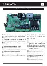
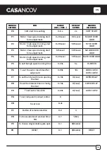
SIDE terminal is used for connecting any external device that operates double gate.
COM terminal is COMMON used for connecting the “ground” of external devices.
SIDE terminal is used for connecting any external device that operates single gate.
Swipe Card terminal is used for connecting any external devices that will operate to
open the gate.
COM terminal is COMMON used for connecting the “ground” of external devices.
Infrared terminal is used for connecting photo electric sensor.
12V DC output is used for connecting photo electric sensor (Continuous output cur-
rent <=200mA).
24V battery output is used for connecting the back up b.
24V battery output is used for connecting the back up battery -.
24V DC output is used for connecting external device. (such as photo electric sensor,
max current output 1A).
GND is used for connecting the “ground” of external devices.
24V DC lamp output is used for connecting flash light +.
24V DC lamp output is used for connecting flash light -.
24V DC lock output—the NF terminal which used for connecting the electric lock.
COM is COMMON used for connecting the “ground” of lock.
24V DC lock output—the NA terminal which used for
connecting the magnetic lock.
24V DC alarm output.
24V DC alarm output.
Motor1 terminal is used for connecting the motor 1 installed
on the gate that opens later and close first. This terminal
connect 1st red wire (from your left hand side to right hand
side).
Motor2 Delay terminal is used for connecting the motor 2
installed on the gate that opens first and close later. This ter-
minal connect 1st blue wire ( from your left hand side to right
hand side). NOTE! If for single gate, the gate motor just can
connect the Motor2 Delay terminal.
AC24V input is used for connecting the transformer.
AC24V input is used for connecting the transformer.
Digital display is used for showing you the setting data.
INC+ is used for figure increase when setting the data.
FUN is used for recorde the data.
DEC- is used for figure decrease when setting the data.
Learning button is used for program/remove remote.
Control board wiring diagram
1 2 3 4 5 6 7
8 9 10 11 12 13 14 15 16 17 18
19
20
20 21
22
22
23
24
25
26
27
28
29
Summary of Contents for HICKER B200
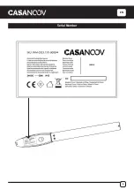
Page 5: ...EN 5 Serial Number ...
Page 10: ...EN 10 Installation of Extended End Motor Arms to Gates USE BUBBLE LEVEL K D mm ...
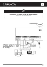
Page 17: ...EN 17 IR OUT COM COM 12V 05 COM 06 IR 07 12V 19 20 21 22 BLUE BROWN BROWN BLUE 19 20 21 22 ...
Page 27: ...FR 27 Numéro de série ...
Page 32: ...FR 32 Installation des bras motorisés sur le portail K D UTILISER UN NIVEAU mm ...
Page 39: ...FR 39 IR OUT COM COM 12V 05 COM 06 IR 07 12V 19 20 21 22 19 20 21 22 BLEU MARRON BLEU MARRON ...
Page 49: ...DE 49 Seriennummer ...
Page 61: ...DE 61 IR OUT COM COM 12V 05 COM 06 IR 07 12V 19 20 21 22 BLAU BRAUN BRAUN BLAU 19 20 21 22 ...
Page 71: ...ES 71 Número de serie ...
Page 83: ...ES 83 IR OUT COM COM 12V 05 COM 06 IR 07 12V 19 20 21 22 AZUL MARRÓN MARRÓN AZUL 19 20 21 22 ...
Page 93: ...PT 93 Número de série ...
Page 115: ...IT 115 Numéro de série ...
Page 127: ...IT 127 IR OUT COM COM 12V 05 COM 06 IR 07 12V 19 20 21 22 BLU MARRONE MARRONE BLU 19 20 21 22 ...
Page 137: ...NL 137 Serienummer ...
Page 149: ...NL 149 IR OUT COM COM 12V 05 COM 06 IR 07 12V 19 20 21 22 BLAUW BRUIN BRUIN BLAUW 19 20 21 22 ...
Page 159: ...PL 159 Numer seryjny ...
Page 164: ...PL 164 Instalacja ramion silnika z przedłużonym końcem do bramek D UŻYWAĆ POZIOM BĄBELKÓW mm ...


