EN
18
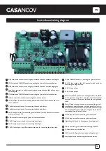
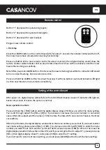
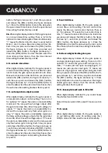
Button “1” depressed to operate single gate;
Button “2” depressed to operate double gate;
Button “3” depressed for alarm output
Program new remote control:
> First step
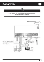
Press the LEARN button on the control board [29] for about 1 second, the indicator LED would turn off,
then now means have already enter learning Second step:
Press any button of the new remote control for about 2 second, then digital display would show the
remote number while indicator LED on board starts flash four times with one buzzer sound then now
means the learning successfully.
Note! After you press LEARN button, if not receive the new remote signal within 5s, indicator LED would
turn on and exit learning. Remove remote control:
Press and hold the LEARN button for about 5 second, if with one buzzer sound and indicator LED light
on, then now means remove remote successfully.
After power on, digital display will self-check from 00-99 with buzzer sound. If indicator LED light on,
buzzer stop sound, it means the system is normal.
Basic operation method:
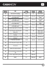
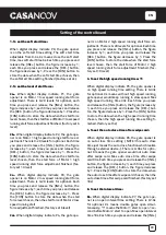
Press and hold the [ FUN] button until the digital display shows PO. Now you enter the menu setting.
You could through adjust the [INC+] [DEC-] to increase or decrease the serial number or numerical
value. After data adjust well then press [ FUN] to store the data. With one sound of buzzer, the store
successfully.
After store the data, the digital display would still on the menu number you just set, if you need to enter
next menu setting, please press [INC+] or [DEC-] to choose and confirm with [FUN] to enter the menu
number you want to set. Such as after you store the P0 value and press [FUN] to store it, then now the
digital display would still show the number P0, and if you want go further to adjust P1, please press one
[INC+], then digital display show P1, later press [FUN] to enter the P1 setting.
If you not need to enter next menu setting, you could press [LEARN] button to exit the menu setting.
Remote control
Setting of the control board
Summary of Contents for HICKER B200
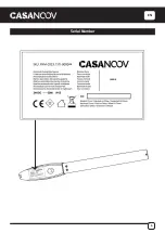
Page 5: ...EN 5 Serial Number ...
Page 10: ...EN 10 Installation of Extended End Motor Arms to Gates USE BUBBLE LEVEL K D mm ...
Page 17: ...EN 17 IR OUT COM COM 12V 05 COM 06 IR 07 12V 19 20 21 22 BLUE BROWN BROWN BLUE 19 20 21 22 ...
Page 27: ...FR 27 Numéro de série ...
Page 32: ...FR 32 Installation des bras motorisés sur le portail K D UTILISER UN NIVEAU mm ...
Page 39: ...FR 39 IR OUT COM COM 12V 05 COM 06 IR 07 12V 19 20 21 22 19 20 21 22 BLEU MARRON BLEU MARRON ...
Page 49: ...DE 49 Seriennummer ...
Page 61: ...DE 61 IR OUT COM COM 12V 05 COM 06 IR 07 12V 19 20 21 22 BLAU BRAUN BRAUN BLAU 19 20 21 22 ...
Page 71: ...ES 71 Número de serie ...
Page 83: ...ES 83 IR OUT COM COM 12V 05 COM 06 IR 07 12V 19 20 21 22 AZUL MARRÓN MARRÓN AZUL 19 20 21 22 ...
Page 93: ...PT 93 Número de série ...
Page 115: ...IT 115 Numéro de série ...
Page 127: ...IT 127 IR OUT COM COM 12V 05 COM 06 IR 07 12V 19 20 21 22 BLU MARRONE MARRONE BLU 19 20 21 22 ...
Page 137: ...NL 137 Serienummer ...
Page 149: ...NL 149 IR OUT COM COM 12V 05 COM 06 IR 07 12V 19 20 21 22 BLAUW BRUIN BRUIN BLAUW 19 20 21 22 ...
Page 159: ...PL 159 Numer seryjny ...
Page 164: ...PL 164 Instalacja ramion silnika z przedłużonym końcem do bramek D UŻYWAĆ POZIOM BĄBELKÓW mm ...


