background image

ERIODIC MAINTENANCE

P

12

6801202

100-Hour Maintenance

Every time the lift truck is service or every 100 hours of 

truck operation, whichever comes first, complete the 

following maintenance on the attachment:

Check for loose or missing fasteners, worn or damaged 

• 

hoses and hydraulic leaks.
Inspect front bin stops for damage.  If front stops do not 

• 

go all the way down, loosen the domed nut jam nuts.  

Turn the outer nut CW 1/4 turn.  Tighten nuts and test.
Check that the fork pin detent locks when engaged.

• 

500-Hour Maintenance

After each 500 hours of truck operation, in addition to the 

100-hour maintenance, perform the following procedures.

Inspect tilt cylinder pivot pin retainers.  If necessary 

• 

tighten capscrews to 8–9.5 ft.-lbs. (11–13 Nm).
Inspect the front bin stop rod and bushings for wear. 

• 

Replace as necessary.
Inspect tilt frame pivot pin and bushings for wear.  

• 

Replace as necessary.  Tighten retainer capscrews to 

8–9.5 ft.-lbs. (11–13 Nm).
Verify that the tilt frame rotates to 135

• 

°

.  If necessary 

adjust locknut located underneath the attachment.

1000-Hour Maintenance

After each 1000 hours of truck operation, in addition to 

the 100 and 500-hour maintenance, perform the following 

procedures.

Inspect lower frame and lift cylinder bearings for 

• 

wear.  Replace as necessary.  If the bearing is worn 

to less than 3/32 in. (2.5 mm) thickness, replace the 

bearing set.  Refer to service manual for replacement 

procedure.
Inspect lift cylinder cap for wear.  Replace as 

• 

necessary.

WARNING

: After completing any service 

procedure, always test each function 

through five complete cycles.  First test with 

no load, then test with a load to make sure 

the attachment operates correctly before 

returning it to the job.

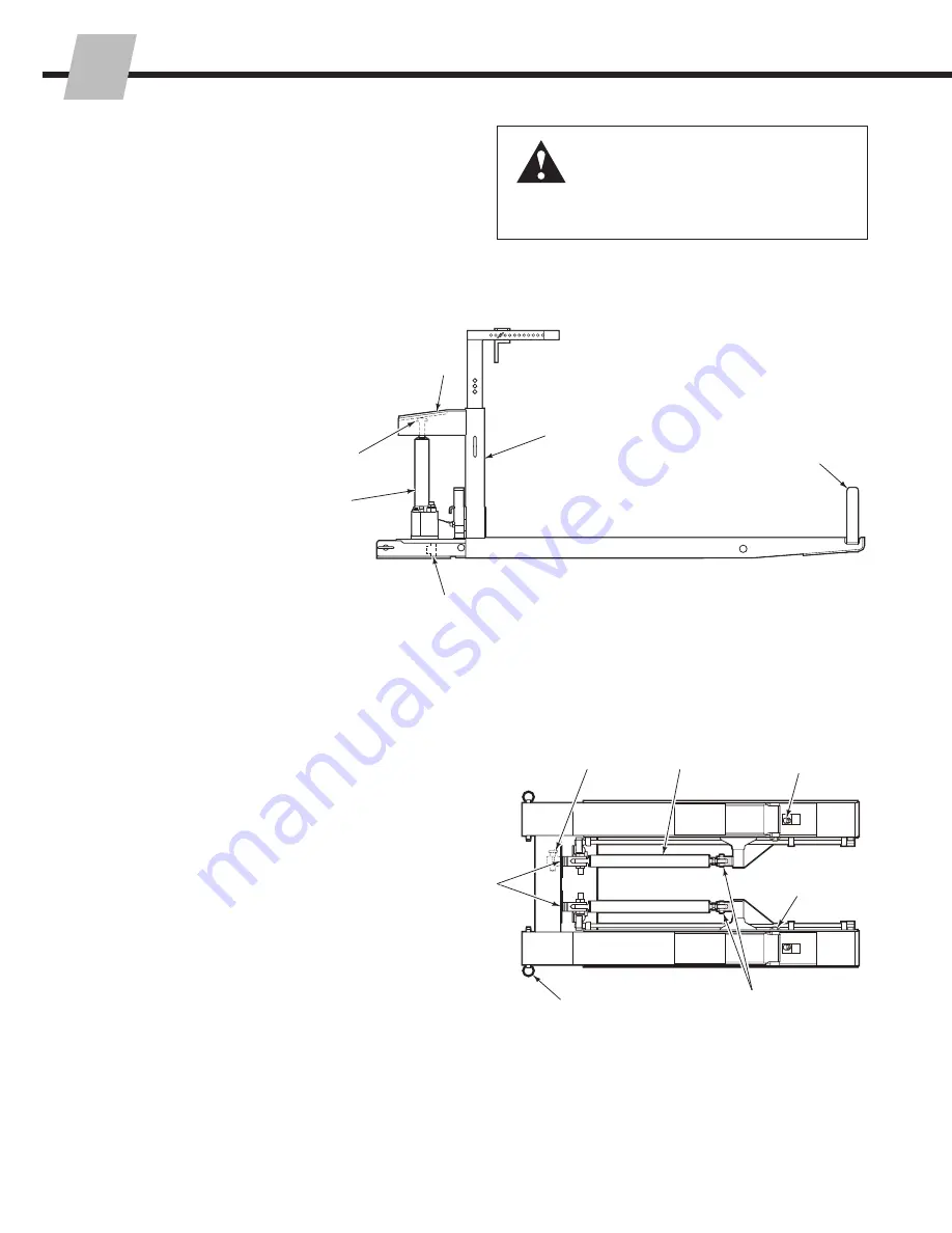
BD0165.eps

BD0166.eps

Bottom View

Side View

Lift 

Cylinder 

Bearing

Lift Cylinder 

Cap

Lift Cylinder

Upper Frame

Assembly

Front Bin 

Stops

Lower Frame 

Bearing

Bin Stop Rod 

and Bushing

Tilt Cylinders

Tilt Frame 

Pivot Pins

Cylinder Rod Ends and 

Pivot Pin Retainers

Tilt Adjuster 

Lock Nut

Fork Pin

Lower 

Frame 

Bearings

Summary of Contents for 10A Bin

Page 1: ...cascade corporation Cascade is a Registered Trademark of Cascade Corporation SER MANUAL U Manual Number 6801202 10A Bin Dumper ...

Page 2: ...on 4 Bin Dumper Operation Auxiliary Valve Functions 4 Picking Up Dumping Loads 5 Safe Operation and Maintenance 6 OSHA Regulations 6 INSTALLATION Recommended Hydraulic Supply 7 Truck Requirements 8 Attachment Installation 9 PERIODIC MAINTENANCE 100 Hour Maintenance 12 500 Hour Maintenance 12 1000 Hour Maintenance 12 2000 Hour Maintenance 13 ...

Page 3: ...k attachment combination is a responsibility of the original truck manufacturer and may be less than shown on the attachment nameplate Consult the truck nameplate WARNING Do not operate this attachment unless you are a trained and authorized lift truck driver This section contains operating instructions for the Cascade 10A Bin Dumper It will help you avoid common errors which often cause damage to...

Page 4: ...turning on ramp Watch clearances Motor off park lower load Traveling empty No reaching through mast No standing under load Tilt Raise Observe Wet floors Workers Stops Bumps Dips Sound horn slow at intersection Sound horn slow at corner Slow for two way traffic With load No load P P P 3 in 8 cm RAMPS TRAFFIC STOP ...

Page 5: ...s No Stand Zone 12 ft 4 m dia Limit truck movement with raised bin Load weight must not exceed combined truck attachment capacity see truck nameplate Center bin prior to lifting traveling or dumping No loads on top of bin Adjust stops to top of bin BD0167 eps ...

Page 6: ...ns Check items each day Report problems to your supervisor See service manual for maintenance and repair procedures BD0148 eps Hydraulic Leaks A Dumper Forward B Dumper Back Fasteners Forks Bin Stops Safety Decals Fork Pin Engagement BD0164 eps A B Hoist Down Tilt Forward Hoist Up Tilt Back A B ...

Page 7: ...vel bin raise for dump clearance B Raise bin clear of ground B Move control lever forward to dump load WIDTH LENGTH Adjust stops Height Allow up to 1 5 in 38 mm clearance with top of bin Length Allow maximum 25 6 mm clearance from front bin stops BD0150 eps BD0151 eps 4 in 10 cm BD0152 eps 3 4 Watch Clearance B Move control level forward 1 second to engage front bin stops A ...

Page 8: ...s view the load engaging means shall be fully lowered controls neutralized and the brakes set to prevent movement 6 A safe distance shall be maintained from the edge of ramps or platforms while on any elevated dock or platform or freight car Trucks shall not be used for opening or closing freight doors 10 A load backrest extension shall be used whenever necessary to minimize the possibility of the...

Page 9: ...se Cable Reel Selection Guide Part No 212199 to select the correct hose reel for the mast and truck Hose and fitting requirements are as follows Hoses and fittings for dump function should be at least No 6 with 9 32 in 7 mm minimum ID C B A A RH THINLINETM 2 Port Hose Reel Group OR B LH THINLINETM 2 Port Hose Reel Group OR C Single Internal Hose Reeving Group GA0033 eps ...

Page 10: ...troleum base hydraulic fluid meeting Mil Spec MIL 0 5606 or MIL 0 2104B Use of synthetic or aqueous base hydraulic fluid is not recommended If fire resistant hydraulic fluid is required special seals must be used Contact Cascade Flow less than recommended will result in slower than normal dumping speed Flow greater than maximum can result in excessive heating reduced system performance and short h...

Page 11: ...epare Hoses A Determine hose lengths required for hydraulic supply B Cut hoses to length install end fittings or quick disconnect kits BD0154 eps BD0155 eps BD0156 eps Extend Extend Retract Retract Quick Disconnect Fittings Quick Disconnect Fittings Hose Terminal Bin Dumper Valve Single Internal Hose Reeving RH shown Hose Reel RH shown ...

Page 12: ... with union fittings B Operate auxiliary valves for 30 seconds C Remove union fittings GA0092 eps 4 Mount bin dumper A Position forks behind bin dumper B Drive forward inserting forks into rear fork pockets C Install fork pins behind fork heel BD0157 eps BD0158 eps C Top View Install fork pins A B ...

Page 13: ...ty bin cycle dumper forward and back several times Check for operation in accordance with ITA ISO standards Check for leaks at fittings valve and cylinders BD0159 eps BD0160 eps GA0010 eps A Dumper Forward B Dumper Back BD0164 eps A B Hoist Down Tilt Forward Hoist Up Tilt Back A B Single Internal Hose Reeving RH shown Hose Reel RH shown ...

Page 14: ... capscrews to 8 9 5 ft lbs 11 13 Nm Verify that the tilt frame rotates to 135 If necessary adjust locknut located underneath the attachment 1000 Hour Maintenance After each 1000 hours of truck operation in addition to the 100 and 500 hour maintenance perform the following procedures Inspect lower frame and lift cylinder bearings for wear Replace as necessary If the bearing is worn to less than 3 3...

Page 15: ...inspection shall be carried out by trained personnel to detect any damage that might impair safe use Any fork that is defective shall be removed from service Reference ANSI B56 1 2005 Inspect for the following defects Surface cracks Straightness of blade and shank Fork angle Difference in height of fork tips Positioning lock Wear on fork blade and shank Wear on fork hooks Legibility of marking NOT...

Page 16: ...Africa Tel 27 11 975 9240 Fax 27 11 394 1147 ASIA PACIFIC Cascade Japan Ltd 2 23 2 Chome Kukuchi Nishimachi Amagasaki Hyogo Japan 661 0978 Tel 81 6 6420 9771 Fax 81 6 6420 9777 Cascade Korea 121B 9L Namdong Ind Complex 691 8 Gojan Dong Namdong Ku Inchon Korea Tel 82 32 821 2051 Fax 82 32 821 2055 Cascade Xiamen No 668 Yangguang Rd Xinyang Industrial Zone Haicang Xiamen City Fujian Province P R Chi...

Reviews: