background image

6

217521 Rev. 0

10

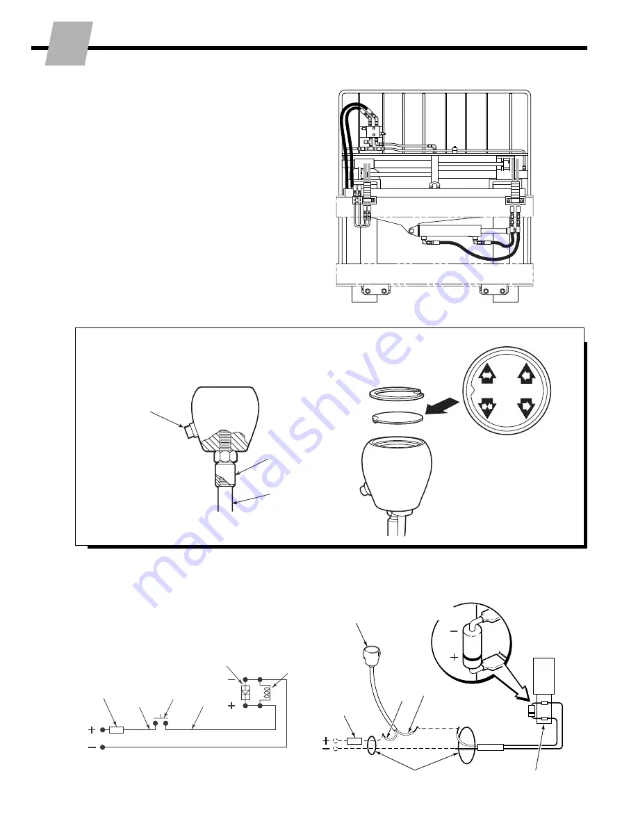
Install wiring –
(Solenoid equipped units)

PRESS 

BUTTON

TO POSITION

SIDESHIFT

CL0240.ill

Button
toward
driver

Truck control
valve handle

Adapter

9

Install solenoid control knob –
(Solenoid equipped units)

CL0258.ill

CL0257.ill

Solenoid Coil

User-supplied wire

7.5-Amp
Fuse

White

Black

7.5-Amp Fuse

White

Black

Solenoid Coil

Diode

Diode

Knob
Button

Control Lever Knob

8

Connect hoses prepared in
Step 6 to Attachment fittings

FP0219.ill

I

NSTALLATION

Summary of Contents for 150H

Page 1: ...Cascade is a Registered Trademark of Cascade Corporation cascadeT Manual Number 217521 NSTALLATION INSTRUCTIONS H Series Fork Positioners I ...

Page 2: ...elow Refer to Cascade Hose Cable Reel Selection Guide Part No 212199 to select the correct hose reel for the mast and truck Hose and fitting requirements are as follows All hoses and fittings for the fork positioning and sideshifting if equipped functions should be No 6 with 9 32 in 7 mm minimum I D This Manual provides instructions for installing Cascade H Series Fork Positioners Follow the sugge...

Page 3: ...68 in 474 5 mm 18 74 in 476 0 mm Class IV 23 44 in 595 5 mm 23 50 in 597 0 mm A Truck Relief Setting 2300 psi 160 bar Recommended 2600 psi 180 bar Maximum Truck Flow Volume 150H Min Recommended Max Fork 3 GPM 4 GPM 5 GPM Position 11 L min 15 L min 19 L min Sideshift 1 GPM 6 GPM 12 GPM 4 L min 23 L min 45 L min Cascade H Series Fork Positioners are compatible with SAE 10W petroleum base hydraulic f...

Page 4: ...nd drop hooks into unlocked position B Reinstall pin in lower hole WARNING Make sure overhead hoist has a rated capacity of at least 2000 lbs 910 kg FP0211 ill cascade C 675514 1 CL0097 ill Tighten Capscrews Class II III Mounting 165 ft lbs 225 Nm Class IV Mounting 190 ft lbs 255 Nm A Pin LH lower Hook NOTE Guides can be reversed to reduce hook to carriage clearance See lower hook installation Ste...

Page 5: ...Inspect hooks for excessive clear ance Reverse guides to reduce clearance see Step 2 Slide hook up to engage bar install pin in locked position upper hole SS0139 ill ADJUST SS0140 ill Lower Carriage Bar Lower Carriage Bar 3 16 in 4 8 mm max Tap tight into position If sideshifter back off 1 notch and check clearance 3 32 in 2 4 mm min 3 16 in 4 8 mm max B ITA Class II 0 32 0 36 in 8 9 mm ITA Class ...

Page 6: ... bottom fork slot to engage forks with carriage D Line up forks with fork carriers on frame E Reinstall frame engaging fork carriers with forks and top carriage bar Tighten mounting capscrews to 115 125 ft lbs 155 170 Nm Mounting Capscrews 4 Fork Carriers B C D A WARNING Remove locking pins from forks Assure that forks slide freely on carriage bars NSTALLATION I Fork Positioner Frame Forks Sideshi...

Page 7: ...REEVING Sideshifting Non sideshifting HOSE REELS Sideshifting Non Sideshifting FP0207 ill Sideshift Right Sideshift Left Close Forks Spread Forks Spread Forks Close Forks FP0208 ill Sideshift Right Sideshift Left 7 Flush hydraulic supply hoses A Install hoses to hose terminals on carriage Connect using union fittings B Operate auxiliary valves for 30 sec C Remove union fittings GA0092 ill Back Dri...

Page 8: ... control valve handle Adapter 9 Install solenoid control knob Solenoid equipped units CL0258 ill CL0257 ill Solenoid Coil User supplied wire 7 5 Amp Fuse White Black 7 5 Amp Fuse White Black Solenoid Coil Diode Diode Knob Button Control Lever Knob 8 Connect hoses prepared in Step 6 to Attachment fittings FP0219 ill I NSTALLATION ...

Page 9: ...0164 ill A B A B FP0164 ill B A C C D D FP0164 ill A B A A B B SIDESHIFTING A Sideshift Left B Sideshift Right C Spread Forks D Close Forks 12 Front View FP0176 ill Flow Restrictor Fittings Valve AUXILIARY VALVE FUNCTIONS Adjust forks for equal movement if required NOTE Attachment is Factory adjusted for equal fork movement when operated at recommended pressure and flow rate A Locate flow restrict...

Page 10: ...n in addition to the 100 and 500 hour maintenance perform the following procedures Inspect fork carrier bearings for wear and replace if necessary Inspect fork cylinder rod anchors for wear and replace if necessary Inspect thickness of of sideshifter if equipped upper bearing sets If either bearing segment is worn to less than 1 16 in 1 5 mm thick replace the bearing set Inspect exposed thickness ...

Page 11: ...Industrielle Sud or B P 22 91421 Morangis Cedex France Tel 1 64547501 FAX 1 9790584 Cascade Hispania S A Avenida De La Fabregada 7 Hospitalet De Llobregat Barcelona Spain Tel 3 335 5158 FAX 3 335 4756 Cascade Canada Inc 5570 Timberlea Blvd Mississauga Ontario Canada L4W 4M6 Tel 905 629 7777 FAX 905 629 7785 Cascade GmbH D 41199 Monchengladbach Klosterhofweg 52 Germany Tel 21 66 602091 FAX 21 66 68...

Reviews: