10
6028021 Rev. 1
NSTALLATION
I
B D
C
A
GA0005.ill
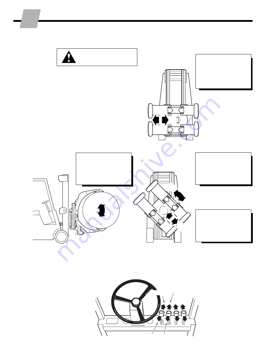
SHORT ARM
(45 degree position only)
C
Open
D
Close
RC1550.ill
C
D
RC1549.ill
C
A
B
D
IMPORTANT:
Make sure hydraulic system
is purged of air before checking attachment
functions outlined below (see Step 9).
•
With no load, cycle all functions several
times.
•
Check functions for operation in accor-
dance with ITA (ISO) standards.
•
Clamp and rotate a maximum load, check
for smoothness and normal rotation.
•
Check for leaks at fittings, revolving
connection and cylinder rod ends.
AUXILIARY VALVE FUNCTIONS
ROTATE
(Driver's view)
A
Counterclockwise (CCW)
B
Clockwise (CW)
Hoist Down
Tilt Forward
Hoist Up
Tilt Back
WARNING:
Make sure all
personnel are clear of the
clamp during testing.
10
SWING
(Bilge handling shown)
A
(Push button) Extend
B
(Push button) Retract
RC0963.ill
LONG ARM
(vertical & horizontal
positions only)
C
Release
D
Clamp
A
B
Cycle attachment functions
NOTE:
Extension or retraction of swing
cylinder swings attachment up or down,
left or right, depending on which orienta-
tion clamp arms are rotated to.


