DISTRIBUTION SYSTEMS - HIGH-FLOW HYDRAULIC POWER SYSTEM
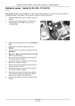
Control valve - Remove (A.16.A.14 - F.10.A.10)
435, 445, 445CT
1.
Remove the cap from the hydraulic reservoir and
install the
CAS1871
adapter on the reservoir.
2.
Connect the
CAS10192
vacuum pump to the
adapter.
Reservoir - Apply vacuum (A.10.A.22 -
F.35.A.50)
3.
Start the vacuum pump.
4.
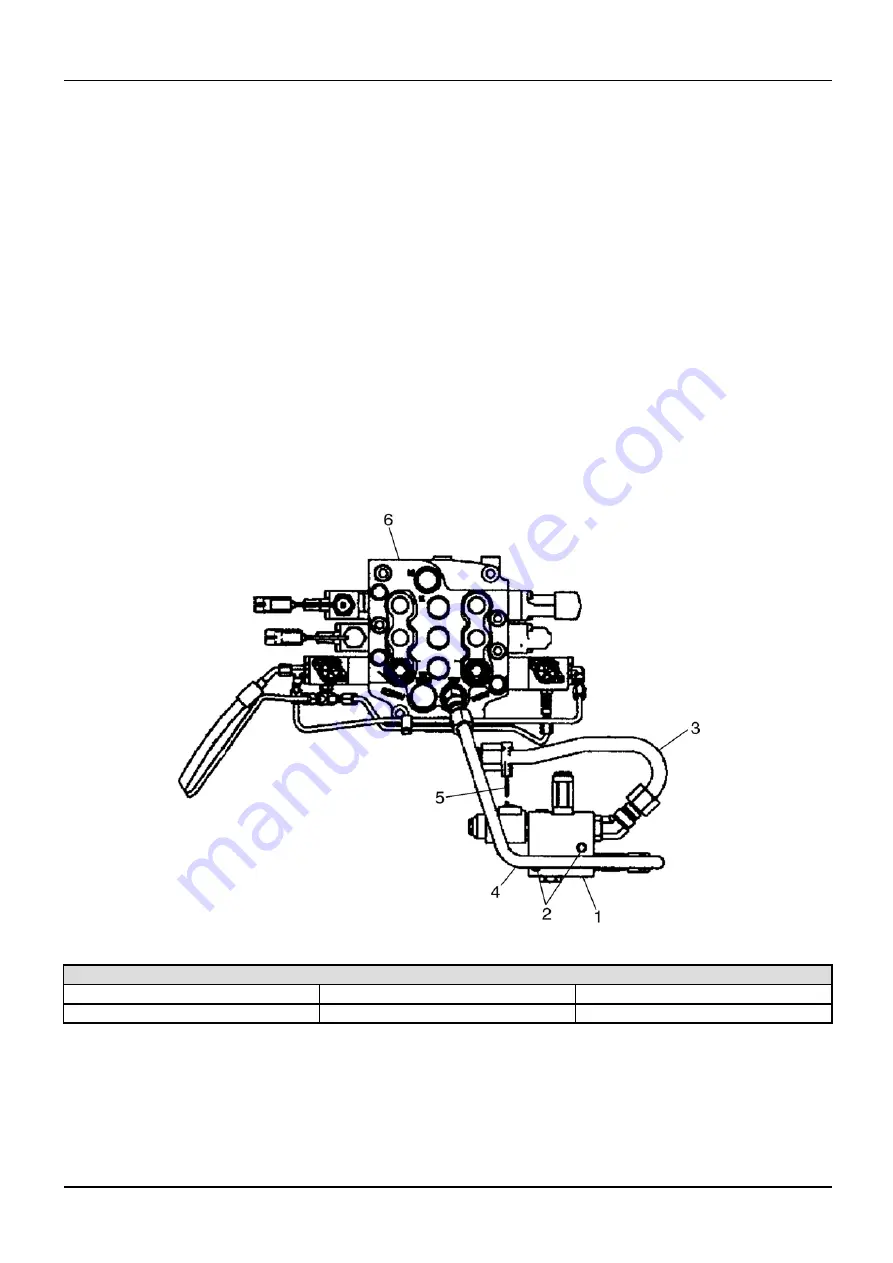
Loosen and remove the hydraulic lines
(3)
and
(4)
from the control valve
(1)
.
5.
Place caps on the
fi
ttings and plugs in the lines.
6.
Stop the vacuum pump.
7.
Disconnect the electrical harness
(5)
from the
control valve electrical connector.
8.
Loosen and remove the mounting bolts
(2)
from the
control valve
(1)
.
9.
Remove the control valve
(1)
from the machine.
bs04d135
1
High-Flow Control Valve
1. High-Flow Control Valve
3. Hydraulic Line
Electrical Harness
2. Mounting Bolts
4. Hydraulic Line
6. Loader Control Valve
1 04/05/2005
A.16.A / 11
Summary of Contents for 435
Page 1: ...REPAIR MANUAL 435 445CT 445 6 75491 1 04 05 2005 ...
Page 3: ...INTRODUCTION 6 75491 1 04 05 2005 1 ...
Page 15: ...INTRODUCTION bs04e020_1 4 6 75491 1 04 05 2005 13 ...
Page 16: ...INTRODUCTION bs04e021_1 5 6 75491 1 04 05 2005 14 ...
Page 19: ...REPAIR MANUAL DISTRIBUTION SYSTEMS 435 445CT 445 39702 1 04 05 2005 A ...
Page 86: ...39703 1 04 05 2005 A 10 A 66 ...
Page 104: ...39704 1 04 05 2005 A 12 A 18 ...
Page 126: ...39705 1 04 05 2005 A 16 A 22 ...
Page 127: ...DISTRIBUTION SYSTEMS A ELECTRICAL POWER SYSTEM 30 A 435 445CT 445 39706 1 04 05 2005 A 30 A 1 ...
Page 237: ...DISTRIBUTION SYSTEMS A LIGHTING SYSTEM 40 A 435 445CT 445 39707 1 04 05 2005 A 40 A 1 ...


