background image

SERVICE

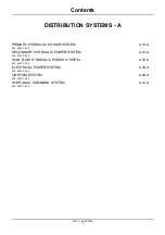
PRIMARY HYDRAULIC POWER SYSTEM - Cleaning (A.10.A - F.30.A.10)

435, 445, 445CT

21

PRIMARY HYDRAULIC POWER SYSTEM - Decontaminating (A.10.A - F.30.A.60)

435, 445, 445CT

25

Relief valve

Relief valve - Flow test (A.10.A.16 - F.40.A.45)

435, 445, 445CT

27

Relief valve - Pressure test (A.10.A.16 - F.40.A.30)

435, 445, 445CT

29

Hydraulic pump

Hydraulic pump - Flow test (A.10.A.20 - F.40.A.45)

435, 445, 445CT

30

Hydraulic pump - Remove (A.10.A.20 - F.10.A.10)

435, 445, 445CT

32

Hydraulic pump - Disassemble (A.10.A.20 - F.10.A.25)

435, 445, 445CT

34

Hydraulic pump - Visual inspection (A.10.A.20 - F.40.A.10)

435, 445, 445CT

39

Hydraulic pump - Assemble (A.10.A.20 - F.10.A.20)

435, 445, 445CT

41

Hydraulic pump - Install (A.10.A.20 - F.10.A.15)

435, 445, 445CT

46

Charge pump

Charge pump - Pressure test (A.10.A.21 - F.40.A.30)

435, 445, 445CT

49

Reservoir

Reservoir - Apply vacuum (A.10.A.22 - F.35.A.50)

435, 445, 445CT

53

Reservoir - Filling (A.10.A.22 - F.60.A.10)

435, 445, 445CT

54

Oil

fi

lter

Oil

fi

lter - Remove (A.10.A.24 - F.10.A.10)

435, 445, 445CT

55

Oil

fi

lter - Install (A.10.A.24 - F.10.A.15)

435, 445, 445CT

57

Oil

fi

lter - Visual inspection (A.10.A.24 - F.40.A.10)

435, 445, 445CT

58

Oil cooler

Oil cooler - Remove (A.10.A.32 - F.10.A.10)

435, 445, 445CT

59

Oil cooler - Install (A.10.A.32 - F.10.A.15)

435, 445, 445CT

62

DIAGNOSTIC

Sensing system

Sensing system Temperature sensor - Testing (A.10.A.95.90 - G.40.A.20)

435, 445, 445CT

63

Sensing system Filter restriction sensor - Testing (A.10.A.95.94 - G.40.A.20)

435, 445, 445CT

63

39703 1 04/05/2005

A.10.A / 3

Summary of Contents for 435

Page 1: ...REPAIR MANUAL 435 445CT 445 6 75491 1 04 05 2005 ...

Page 2: ...Contents INTRODUCTION DISTRIBUTION SYSTEMS A POWER PRODUCTION B POWER TRAIN C TRAVELLING D BODY AND STRUCTURE E WORKING ARM H TOOLS AND COUPLERS J 6 75491 1 04 05 2005 ...

Page 3: ...INTRODUCTION 6 75491 1 04 05 2005 1 ...

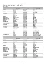
Page 4: ...Contents INTRODUCTION Basic instructions A 90 A 05 435 445 445CT 3 Torque A 90 A 10 435 445 7 Consumables A 92 A 55 435 445 445CT 11 Conversion factors A 92 A 21 435 445 445CT 15 6 75491 1 04 05 2005 2 ...

Page 5: ...technical information during the authoring process The first category is the Location the second category is the Information Type and the third category is the Product LOCATION is the component or function on the machine that the piece of technical information is going to describe e g Fuel tank INFORMATION TYPE is the piece of technical information that has been written for a particular component ...

Page 6: ...Combines forage harvesters balers X X X X X X X X X X Seeding planting floating spraying equipment X X X X X X X X X Mounted equipment and tools X X X X Chapters Each Chapter is identified by a letter and number combination e g Engine B 10 A The first letter is identical to the Section letter i e Chapter B 10 is inside Section B Power Production CONTENTS The Chapter Contents lists all the technica...

Page 7: ...e classification Distribution systems Primary hydraulic power Stack valve Functional data Sectional view CRIL03J033E01 1 Navigate to the correct information unit you are searching for by identifying the function and information type from the ICE code 1 Function and 2 Information type A corresponds to the sections of the repair manual B corresponds to the chapters of the repair manual C corresponds...

Page 8: ...g references Section and Chapter description The page footer will contain the following references Publication number for that Manual Section or Chapter Version reference for that publication Publication date Section chapter and page reference e g A 10 A 9 6 75491 1 04 05 2005 6 ...

Page 9: ...Cap Screws 2 5 8 L9 Alloy SAE Markings for Hex Nuts GRADE 2 GRADE 5 5 1 or 5 2 GRADE 8 or 8 2 GRADE L9 Alloy Dry Lubricated Dry Lubricated Dry Lubricated Head Nut SIZE Nm lb ft Nm lb ft Nm lb ft Nm lb ft Nm lb ft Nm lb ft Nm lb ft Nm lb ft 1 4 UNF 7 5 5 5 5 7 4 2 10 8 8 8 5 6 3 16 3 12 12 2 9 13 6 10 14 9 11 1 4 UNC 8 5 6 3 6 4 4 7 13 6 10 9 8 7 2 19 14 13 6 10 16 3 12 17 6 13 5 16 UNF 15 11 11 8 ...

Page 10: ...180 870 881 650 2644 1950 1980 1460 4285 3160 3214 2370 3932 2900 4407 3250 1 1 2 UNC 1329 980 990 730 2983 2200 2224 1640 4827 3560 3621 2670 4475 3300 4949 3650 IMPORTANT DO NOT use these values if a different torque value or tightening procedure is given for a specific application Torque values listed are for general use only Check tightness of fasteners periodically Shear bolts are designed to...

Page 11: ...to 21 156 to 192 6 9 5 mm 3 8 inch 9 16 18 27 to 33 240 to 300 8 12 7 mm 1 2 inch 3 4 16 46 56 408 to 504 10 15 9 mm 5 8 inch 7 8 14 77 to 85 684 to 756 12 19 0 mm 3 4 inch 1 1 16 12 107 to 119 79 to 88 14 22 2 mm 7 8 inch 1 3 16 12 127 to 140 94 to 103 16 25 4 mm 1 0 inch 1 5 16 12 131 to 156 97 to 117 20 31 8 mm 1 1 4 inch 1 5 8 12 197 to 223 145 to 165 24 38 1 mm 1 1 2 inch 1 7 8 12 312 to 338 ...

Page 12: ...o 684 10 7 8 14 102 to 114 75 to 84 12 1 1 16 12 142 to 160 105 to 117 16 1 5 16 12 237 to 254 175 to 187 Pipe Fitting Nom SAE Dash Size Thread Size TFFT Turns For Finger Tight 2 1 8 27 2 0 3 0 3 1 8 27 2 0 3 0 4 1 8 27 2 0 3 0 5 1 8 27 2 0 3 0 6 1 4 18 1 5 3 0 8 3 8 18 2 0 3 0 10 1 2 14 2 0 3 0 12 3 4 14 2 0 3 0 14 3 4 14 2 0 3 0 16 1 11 1 2 1 5 2 5 20 1 1 4 11 1 2 1 5 2 5 24 1 1 2 11 1 2 1 5 2 5...

Page 13: ...for correct disposal information BS00H001 1 Engine Oil Selection Case No 1 Engine Oil is recommended for use in your Case Engine Case Engine Oil will lubricate your engine correctly under all operating conditions RH99K130 2 See the chart below for recommended viscosity at ambient temperature ranges NOTE Do not put Performance Additives or other oil additive products in the engine crankcase The oil...

Page 14: ...se of oil fluids and lubricants always remember the environment Do not put oil or fluids into the ground or into containers that can leak Check with your local environmental recycling center or your Case dealer for correct disposal information 6 75491 1 04 05 2005 12 ...

Page 15: ...INTRODUCTION bs04e020_1 4 6 75491 1 04 05 2005 13 ...

Page 16: ...INTRODUCTION bs04e021_1 5 6 75491 1 04 05 2005 14 ...

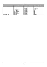
Page 17: ...061 024 35 314 66 1 307 950 0 033 814 1 056 814 0 879 877 0 264 172 0 219 969 cubic inch cubic foot cubic yd ounce US fluid quart US liquid quart Imperial gallon US liquid gallon Imperial VOLUME TIME litre min litre min 0 264 172 0 219 969 gallon min US liquid gallon min Imperial U S to Metric MULTIPLY BY TO OBTAIN AREA square foot acre 0 092 903 0 404 686 square meter hectare FORCE ounce force po...

Page 18: ...nce US fluid quart US liquid quart Imperial gallon US gallon Imperial 16 387 06 0 028 317 0 764 555 29 573 53 0 946 353 1 136 523 3 785 412 4 546 092 cubic centimeter cubic meter cubic meter milliliter litre litre litre litre VOLUME TIME gallon min 3 785 412 litre min 6 75491 1 04 05 2005 16 ...

Page 19: ...REPAIR MANUAL DISTRIBUTION SYSTEMS 435 445CT 445 39702 1 04 05 2005 A ...

Page 20: ...5CT 445 A 10 A SECONDARY HYDRAULIC POWER SYSTEM 435 445CT 445 A 12 A HIGH FLOW HYDRAULIC POWER SYSTEM 435 445CT 445 A 16 A ELECTRICAL POWER SYSTEM 435 445CT 445 A 30 A LIGHTING SYSTEM 435 445CT 445 A 40 A HYDRAULIC COMMAND SYSTEM 435 445CT 445 A 14 A 39702 1 04 05 2005 A ...

Page 21: ...DISTRIBUTION SYSTEMS A PRIMARY HYDRAULIC POWER SYSTEM 10 A 435 445CT 445 39703 1 04 05 2005 A 10 A 1 ...

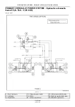
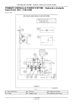
Page 22: ...TEM Hydraulic schematic frame 01 A 10 A C 20 H 01 435 445 445CT 9 PRIMARY HYDRAULIC POWER SYSTEM Hydraulic schematic frame 02 A 10 A C 20 H 02 435 445 445CT 10 PRIMARY HYDRAULIC POWER SYSTEM Hydraulic schematic frame 03 A 10 A C 20 H 03 435 445 445CT 12 PRIMARY HYDRAULIC POWER SYSTEM Hydraulic schematic frame 04 A 10 A C 20 H 04 435 445 445CT 14 PRIMARY HYDRAULIC POWER SYSTEM Hydraulic schematic f...

Page 23: ...0 435 445 445CT 41 Hydraulic pump Install A 10 A 20 F 10 A 15 435 445 445CT 46 Charge pump Charge pump Pressure test A 10 A 21 F 40 A 30 435 445 445CT 49 Reservoir Reservoir Apply vacuum A 10 A 22 F 35 A 50 435 445 445CT 53 Reservoir Filling A 10 A 22 F 60 A 10 435 445 445CT 54 Oil filter Oil filter Remove A 10 A 24 F 10 A 10 435 445 445CT 55 Oil filter Install A 10 A 24 F 10 A 15 435 445 445CT 57...

Page 24: ...445CT Hydraulic System Oil Type of Oil Capacity Total System 435 Machines CASE AKCELA NO 1 ENGINE OIL SAE 10W 30 41 3 L 10 9 US gal Total System 445 445CT Machines CASE AKCELA NO 1 ENGINE OIL SAE 10W 30 41 5 L 11 US gal Total System 450 450CT Machines CASE AKCELA NO 1 ENGINE OIL SAE 10W 30 64 4 L 17 US gal Total System 465 Machines CASE AKCELA NO 1 ENGINE OIL SAE 10W 30 66 2 L 17 5 US gal Chain Ta...

Page 25: ...DISTRIBUTION SYSTEMS PRIMARY HYDRAULIC POWER SYSTEM CAS1808 2 CAS 1808 Flowmeter Fitting Kit CAS10090 3 CAS 10090 Hand Pump B877558M_1 4 CAS 1804 Pressure Test Fitting Kit 1 04 05 2005 A 10 A 5 ...

Page 26: ...RAULIC POWER SYSTEM Relief valve General specification A 10 A 16 D 40 A 10 435 445 445CT Loader Control Valve Relief Pressure Settings Main Relief Pressure at 10 gpm 21290 kPa 210 bar 3050 50 72 5 psi at 2200 RPM 1 04 05 2005 A 10 A 6 ...

Page 27: ...ULIC POWER SYSTEM Hydraulic pump General specification A 10 A 20 D 40 A 10 435 445 445CT Hydraulic Pump Type Gear Displacement 36cc 2 2 in Flow at Engine Rated RPM at 100 Volumetric Efficiency 82 9 L min 2 2 US gpm 1 04 05 2005 A 10 A 7 ...

Page 28: ...DISTRIBUTION SYSTEMS PRIMARY HYDRAULIC POWER SYSTEM Oil filter by pass General specification A 10 A 25 D 40 A 10 435 445 445CT Return Filter Bypass Pressure 345 kPa 50 psi 1 04 05 2005 A 10 A 8 ...

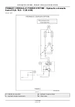
Page 29: ...draulic reservoir 2 Right piston pump 10 Right drive motor 18 Drain manifold 3 Charge pump 11 Left brake 21 Backup alarm switch ports 4 Hydrostatic pump 12 Right brake 22 Brake light switch ports 5 Circuit relief valve 13 Flushing valve 25 Main relief valve 6 Tow valve 14 Brake solenoid valve 44 100 Mesh screen 7 Check valve 15 Charge pressure switch 8 Hydraulic pump 16 Orifice 1 04 05 2005 A 10 A...

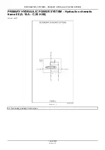
Page 30: ...OWER SYSTEM PRIMARY HYDRAULIC POWER SYSTEM Hydraulic schematic frame 02 A 10 A C 20 H 02 435 445 445CT bc04h207 02 1 5 Circuit relief valve 23 Tilt cylinders 28 Lift spool 26 Orifice 24 Lift cylinders 29 Auxiliary spool 1 04 05 2005 A 10 A 10 ...

Page 31: ...DISTRIBUTION SYSTEMS PRIMARY HYDRAULIC POWER SYSTEM 19 Oil cooler 26 Loader control valve 30 Auxiliary outlets 20 Oil cooler bypass valve 27 Tilt spool 1 04 05 2005 A 10 A 11 ...

Page 32: ...ic schematic frame 03 A 10 A C 20 H 03 435 445 445CT bc04h207 03 1 5 Circuit relief valve 15 Charge pressure switch 33 Left two speed shuttle valve 11 Left brake 16 Orifice 34 Right two speed shuttle valve 12 Right brake 31 Left two speed motor 35 Brake two speed valve 1 04 05 2005 A 10 A 12 ...

Page 33: ...DISTRIBUTION SYSTEMS PRIMARY HYDRAULIC POWER SYSTEM 13 Flushing valve 32 Right two speed motor 36 Two speed solenoid valve 14 Brake solenoid valve 1 04 05 2005 A 10 A 13 ...

Page 34: ...TEM PRIMARY HYDRAULIC POWER SYSTEM Hydraulic schematic frame 04 A 10 A C 20 H 04 435 445 445CT bc04h207 04 1 5 Circuit relief valve 28 Lift spool 38 High flow oil cooler 16 Orifice 29 Auxiliary spool 39 High flow control valve 1 04 05 2005 A 10 A 14 ...

Page 35: ...DISTRIBUTION SYSTEMS PRIMARY HYDRAULIC POWER SYSTEM 26 Loader control valve 30 Auxiliary outlets 40 Attachment case drain 27 Tilt spool 37 High flow pump 45 Accumulator 1 04 05 2005 A 10 A 15 ...

Page 36: ...WER SYSTEM PRIMARY HYDRAULIC POWER SYSTEM Hydraulic schematic frame 05 A 10 A C 20 H 05 435 445 445CT bc04h207 05 1 40 Attachment case drain 42 Hydraulic coupler cylinder 41 Hydraulic coupler control valve 46 Check valve 1 04 05 2005 A 10 A 16 ...

Page 37: ...UTION SYSTEMS PRIMARY HYDRAULIC POWER SYSTEM PRIMARY HYDRAULIC POWER SYSTEM Hydraulic schematic frame 06 A 10 A C 20 H 06 435 445 445CT bc04h207 06 1 43 Secondary auxiliary control valve 1 04 05 2005 A 10 A 17 ...

Page 38: ...DISTRIBUTION SYSTEMS PRIMARY HYDRAULIC POWER SYSTEM PRIMARY HYDRAULIC POWER SYSTEM Hydraulic schematic frame 07 A 10 A C 20 H 07 435 445 445CT bc04h207 07 1 47 Self level valve 1 04 05 2005 A 10 A 18 ...

Page 39: ... SYSTEMS PRIMARY HYDRAULIC POWER SYSTEM PRIMARY HYDRAULIC POWER SYSTEM Hydraulic schematic frame 08 A 10 A C 20 H 08 435 445 445CT bc04h207 08 1 45 Accumulator 48 Ride control solenoid valve 1 04 05 2005 A 10 A 19 ...

Page 40: ...l view A 10 A 20 C 10 A 30 435 445 445CT BS98F177 1 1 Gear plate 7 Washer 13 Wear plate 2 Cover 8 Washer 14 Seal 3 Bearing sleeve 9 Dowel pin 15 Seal 4 Body 10 Oil seal 16 Socket bolt 5 Idler shaft 11 Seal ring 17 Socket bolt 6 Drive shaft 12 Wear plate 1 04 05 2005 A 10 A 20 ...

Page 41: ...r rod seals leak B Control valve spools do not return to neutral C Movement of control valve spools is difficult D Hydraulic oil becomes too hot E Pump gears housing and other parts wear rapidly F Relief valves or check valves held open by dirt G Quick failure of components that have been repaired H Cycle times are slow machine does not have enough power 3 If your machine has any of these problems...

Page 42: ...termine whether the contamination is microscopic or visible Refer to PRIMARY HYDRAULIC POWER SYSTEM Decontaminating A 10 A F 30 A 60 9 If the contamination is microscopic A Check the maintenance schedule for the machine to learn if the hydraulic oil must be changed If necessary change the hydraulic oil Change the hydraulic filter B Do steps 12 through 41 10 If the contamination is visible do the f...

Page 43: ...lowing to heat the oil to operating temperature A Increase the engine speed to full throttle B Hold the bucket control lever in the ROLLBACK position for five seconds C Return the blade control lever in the NEUTRAL position for five seconds D Repeat steps 25B and 25C until the oil is at operating temperature 26 With the engine running at full throttle and the portable filter running completely ext...

Page 44: ...the reservoir 40 Install new hydraulic and hydrostatic filter elements on the machine 41 Start the engine Check for oil leakage around the new hydraulic and hydrostatic filters 42 Stop the engine 43 Check the level of the oil in the reservoir and add oil as required Reservoir Filling A 10 A 22 F 60 A 10 1 04 05 2005 A 10 A 24 ...

Page 45: ...and hydrostatic filter elements from the machine 7 Install new hydraulic and hydrostatic filter elements on the machine 8 Install the drain plug in the bottom of the reservoir 9 Fill the hydraulic reservoir Reservoir Filling A 10 A 22 F 60 A 10 10 Disconnect the line from the OPEN end and CLOSED end of each cylinder 11 Be sure all control levers are in the NEUTRAL position 12 Start and run the eng...

Page 46: ...ine 21 Disconnect the drain lines and connect the system lines to the cylinders 22 Check the oil level in the hydraulic reservoir Add oil as required 23 Install the filler cap on the reservoir 24 Remove the hydraulic and hydrostatic filter elements from the machine 25 Install new hydraulic and hydrostatic filter elements on the machine 26 Start and run the engine at 1500 rpm r min operate each hyd...

Page 47: ...the flow indication will decrease slowly As you continue to close the pressure valve you will reach a point at which the flow indication begins to decrease rapidly This is the point at which the main relief valve starts to open Read the pressure gauge and record the reading as test number 5 6 Continue to close the pressure valve until the indication of the flow gauge is zero This is the point at w...

Page 48: ...y the same as the flow indication at the same pressure in Test Number 1 of the Hydraulic Pump Flow Test the circuit is good 12 If the flow indication for a circuit was more than 3 8 L min one gpm less than the flow indication at the same pressure in Hydraulic pump Flow test A 10 A 20 F 40 A 45 Test Number 1 there is leakage in that circuit 1 04 05 2005 A 10 A 28 ...

Page 49: ...ure of the oil is 52 C 125 F or the side of the reservoir is very warm 3 Use a pressure gauge with a capacity of at least 276 bar 4000 psi Connect the pressure gauge to one of the auxiliary hydraulic couplers on the left hand loader arm 4 Run the engine at full throttle Actuate the auxiliary hydraulic flow control pedal to pressurize the hydraulic line which has the pressure gauge Record the indic...

Page 50: ...n the engine at full throttle and close the pressure valve of the flowmeter until the pressure gauge indicates 103 bar 1500 psi Continue to run the engine at full throttle until the temperature of the oil is 52 C 125 F Then open the pressure valve completely 7 Make sure that the pressure valve is opened completely Adjust the engine speed to 2300 r min rpm and read the flow gauge Read the flow and ...

Page 51: ...General specification A 10 A 20 D 40 A 10 there are no problems between the reservoir and the gear pump However the gear pump can be worn or damaged and still have good flow at minimum pressure 14 Loss of output at 152 bar 2200 psi indicates that the gear pump is worn or damaged To determine the efficiency of the gear pump divide the flow indication from test number 4 by the flow indication from t...

Page 52: ...mp 3 Remove the cap from the hydraulic reservoir CAS1871 4 Connect a vacuum pump to the hydraulic reservoir CAS10192 5 Reservoir Apply vacuum A 10 A 22 F 35 A 50 Start the vacuum pump 6 Tag and disconnect the hose from the fitting at the suction port of the gear pump BD04C141x 2 7 Install a plug in the hose and a cap on the fitting 8 Tag and disconnect the hose from the fitting at the pressure por...

Page 53: ...IBUTION SYSTEMS PRIMARY HYDRAULIC POWER SYSTEM 11 Loosen and remove the pump mounting bolts and washers BD04C141x 3 12 Remove the gear pump from the hydrostatic pump mounting location 1 04 05 2005 A 10 A 33 ...

Page 54: ...assemble A 10 A 20 F 10 A 25 435 445 445CT 1 Draw alignment marks on the housing with a white marker These marks will be referenced during assembly GD98J801 1 2 Loosen and remove the socket bolts and washers GD98J802 2 3 Remove the cover GD98J803 3 1 04 05 2005 A 10 A 34 ...

Page 55: ...move the gear plate GD98J804 4 5 Remove the dowel pins GD98J805_2 5 6 Rotate the gear teeth until one gear tooth is centered inside two gear teeth Draw a mark with a white marker This mark will be referenced during assembly GD98J806 6 1 04 05 2005 A 10 A 35 ...

Page 56: ...DISTRIBUTION SYSTEMS PRIMARY HYDRAULIC POWER SYSTEM 7 Remove the drive shaft GD98J807 7 8 Remove the idler shaft GD98J808 8 9 Remove the wear plate from the cover GD98J809 9 1 04 05 2005 A 10 A 36 ...

Page 57: ...RY HYDRAULIC POWER SYSTEM 10 Remove the wear plate from the body GD98J810 10 11 Remove and discard the seal ring from the cover GD98J811_2 11 12 Remove and discard the seal ring from the body GD98J812_2 12 1 04 05 2005 A 10 A 37 ...

Page 58: ...DISTRIBUTION SYSTEMS PRIMARY HYDRAULIC POWER SYSTEM 13 Remove and discard the top seal from the body GD98J813 13 14 Remove and discard the bottom seal from the body GD98J814 14 1 04 05 2005 A 10 A 38 ...

Page 59: ...spection A 10 A 20 F 40 A 10 435 445 445CT 1 Inspect the brass surfaces of the wear plates GD98J815 1 2 Inspect the drive and idler shafts for damage GD98J816 2 3 Inspect the bearing sleeves of the drive and idler shafts in the body and cover GD98J817_2 3 1 04 05 2005 A 10 A 39 ...

Page 60: ...DISTRIBUTION SYSTEMS PRIMARY HYDRAULIC POWER SYSTEM 4 Inspect the body and cover surfaces GD98J818_2 4 1 04 05 2005 A 10 A 40 ...

Page 61: ... Lubricate and insert the bottom seal into the groove of the body GD98J814 1 2 Lubricate and insert the top seal into the groove of the body NOTE The top seal will be placed on top of the bottom seal GD98J813 2 3 Lubricate and insert a new seal ring into the groove of the body GD98J812_2 3 1 04 05 2005 A 10 A 41 ...

Page 62: ...STEM 4 Lubricate and insert a new seal ring into the groove of the cover GD98J811_2 4 5 Place the wear plate on top of the new seals on the body GD98J810 5 6 Place the wear plate on top of the new seal on the cover GD98J809 6 1 04 05 2005 A 10 A 42 ...

Page 63: ... the drive shaft through the wear plate and into the housing GD98J807 8 9 During the gear pump disassembly the gear teeth were aligned and then marked Please refer to Hydraulic pump Disassemble A 10 A 20 F 10 A 25 Ensure that the meshed teeth marks on the drive shaft and the idler shaft are properly aligned GD98J806 9 1 04 05 2005 A 10 A 43 ...

Page 64: ...gear plate down the shafts and guide dowels until it is snug against the body GD98J804 11 12 During the gear pump disassembly alignment marks were placed on the housing for the body and cover Please refer to Hydraulic pump Disassemble A 10 A 20 F 10 A 25 Align and place the cover on top of the body GD98J803 12 1 04 05 2005 A 10 A 44 ...

Page 65: ...DISTRIBUTION SYSTEMS PRIMARY HYDRAULIC POWER SYSTEM 13 Secure the cover on top of the body with washers and socket bolts Tighten the socket bolts Do not overtighten GD98J802 13 1 04 05 2005 A 10 A 45 ...

Page 66: ...mounting flange is flush with the mounting surface of the hydrostatic pump 2 Apply Loctite 243 to the pump mounting bolts Install washers on the bolts and install the bolts into the pump mounting flange Tighten the mounting bolts 3 Reservoir Apply vacuum A 10 A 22 F 35 A 50 Start the vacuum pump 4 Remove the cap from the fitting and the plug from the pressure hose 5 Connect the hose to the pressur...

Page 67: ...e fuel shutoff solenoid connector Photo is for reference only bd04c019 3 12 Turn the engine over for 30 seconds to allow hydraulic oil from the reservoir to flow into the hydraulic pump Reconnect the fuel shutoff solenoid connector 13 Start and run the engine at low idle for 2 to 5 minutes and check for any leaks 14 Stop the engine 15 Check the hydraulic oil level in the reservoir and add hydrauli...

Page 68: ... HYDRAULIC POWER SYSTEM 16 Install the floor plate and the cover plate Install the floor plate and the cover plate mounting bolts and washers Tighten the mounting bolts on the floor plate and the cover plate 1 04 05 2005 A 10 A 48 ...

Page 69: ...essive the charge pressure will drop off more This slight drop in charge pressure between the system in neutral and with the system under load indicates the condition of the closed loop system components 1 Raise and securely block the unit off the ground 2 Remove the brake assist line from the tee fitting at the T port 1 of the brake valve 3 BD03F001_1 1 3 Remove the cap from the tee fitting on th...

Page 70: ... The pressure reading must be 26 28 bar 390 410 psi or the relief valve must be adjusted with shims 12 If the pressure is correct go to step 14 If the pressure is not correct loosen the cap on the hydraulic reservoir Remove the plug shim s spring and poppet for the charge pressure relief valve 13 Inspect the parts of the charge relief valve If the parts are good add shim s from the shim kit part n...

Page 71: ... must be not greater than 138 kPa 1 5 bar 20 psi Any difference greater than 138 kPa 1 5 bar 20 psi indicates excessive leakage from the closed loop which will require repair NOTE The charge pressure drop indicates internal leakage from the system with the system under load This is caused by less oil flowing over the charge relief and therefore the lower pressure Excessive leakage greater than 138...

Page 72: ...he mating component and cause damage As this damage progresses contamination will return to the reservoir through the case drain system At the very least once a failure has occurred the mating component in the hydrostatic system must be inspected for damage If any contamination has been returned to the reservoir tear down and inspection of both complete closed loop systems is necessary since the s...

Page 73: ... Reservoir Apply vacuum A 10 A 22 F 35 A 50 435 445 445CT 1 Remove the cap from the hydraulic reservoir 2 Install an adapter cap on the filler neck CAS1871 3 Connect the vacuum pump to the adapter CAS10192 4 Start the vacuum pump 1 04 05 2005 A 10 A 53 ...

Page 74: ...voir Do not remove the filler cap from the reservoir until the pressure is relieved 4 Remove the filler cap from the reservoir 5 Add the correct oil CASE AKCELA AUTO SUPREME SAE 10W 30 to the reservoir until the proper oil level in the reservoir is established Fill the reservoir until the oil level is at the mid point of the site gauge 6 Start and run the engine and operate the hydraulics Lower th...

Page 75: ...o the reservoir 4 Start the vacuum pump 5 Tag and disconnect all the hydraulic lines to the oil filter base Install plugs in the fittings Loosen and remove the wire from the electrical connector BD04C143 1 6 Stop the vacuum pump 7 Loosen and remove the mounting bolts and washers from the oil filter head mounting bracket BD04C143 2 8 Remove the oil filter head from the mounting bracket 9 Oil filter...

Page 76: ... PRIMARY HYDRAULIC POWER SYSTEM BC01D076 3 Hydraulic Filter Base Assembly 1 Bolt 4 Special washer 7 O ring 10 Filter element 2 Washer 5 Nut 8 O ring 11 O ring 3 Filter head 6 Lock washer 9 Indicator 1 04 05 2005 A 10 A 56 ...

Page 77: ...op the vacuum pump Disconnect the vacuum pump from the hydraulic reservoir and install the reservoir cap on the reservoir filler neck 6 Clean up any hydraulic oil from the equipment and the floor 7 Install the electrical connection onto the mounting stud Install the washer and the mounting nut and tighten the mounting nut 8 Start the engine and run at low idle 9 Operate the loader controls to comp...

Page 78: ...ction A 10 A 24 F 40 A 10 435 445 445CT 1 Inspect the hydraulic oil filter head and bypass switch assembly for any damage Replace any parts as required 2 Inspect the hydraulic filter mounting bracket for corrosion or damage Replace any parts as required 1 04 05 2005 A 10 A 58 ...

Page 79: ...mately 19 litres 5 gallons NOTE During installation fill the radiator and coolant reservoir completely ENGINE COOLANT SYSTEM Capacity B 50 A D 40 A 20 Start and run the engine until the coolant is at operating temperature Stop the engine and check for leakage When the coolant is cold check the coolant reservoir level Add coolant as required BD04C003 2 5 Loosen the hose clamps on the upper and lowe...

Page 80: ...nting location on the oil cooler bdo4c008 4 7 Push the handle on the latch to release the radiator from the oil cooler Tip the radiator down to access the hardware which fastens the radiator to the oil cooler Remove the hardware from the radiator and remove the radiator from the engine compartment bd04c026 5 8 Loosen and remove the bolts which fasten the fan guard to the oil cooler Remove the fan ...

Page 81: ... top of the oil cooler Install plugs and caps on the fittings bd04c010 7 10 Loosen and remove the hydraulic hose fitting from the bottom of the oil cooler Install plugs and caps on the fittings BD04C006 8 11 Stop the vacuum pump 12 Loosen and remove the hardware which fastens the oil cooler to the chassis Remove the oil cooler 1 04 05 2005 A 10 A 61 ...

Page 82: ... the oil cooler is the reverse procedure of Oil Cooler Remove 2 After installation of the oil cooler do the following procedure 3 Start and run the engine at low idle for 2 to 5 minutes and check for any leaks 4 Stop the engine 5 Check the oil level in the hydraulic reservoir and add oil as required Reservoir Filling A 10 A 22 F 60 A 10 1 04 05 2005 A 10 A 62 ...

Page 83: ...r in the wiring harness For oil temperatures greater than 60 F and less than 212 F the sensor resistance should measure between 4300 ohms 60 F and 180 ohms 212 F Temperature of oil outside of range indicated Bad sensor Bad wiring to the sensor Sensing system Filter restriction sensor Testing A 10 A 95 94 G 40 A 20 435 445 445CT NOTE For wiring diagram refer to Wiring harness Electrical schematic f...

Page 84: ...4 F 40 A 10 435 445 445CT 58 Oil filter by pass General specification A 10 A 25 D 40 A 10 435 445 445CT 8 PRIMARY HYDRAULIC POWER SYSTEM Capacity A 10 A D 40 A 20 435 445 445CT 4 PRIMARY HYDRAULIC POWER SYSTEM Cleaning A 10 A F 30 A 10 435 445 445CT 21 PRIMARY HYDRAULIC POWER SYSTEM Decontaminating A 10 A F 30 A 60 435 445 445CT 25 PRIMARY HYDRAULIC POWER SYSTEM General specification A 10 A D 40 A...

Page 85: ...alve General specification A 10 A 16 D 40 A 10 435 445 445CT 6 Relief valve Pressure test A 10 A 16 F 40 A 30 435 445 445CT 29 Reservoir Apply vacuum A 10 A 22 F 35 A 50 435 445 445CT 53 Reservoir Filling A 10 A 22 F 60 A 10 435 445 445CT 54 Sensing system Filter restriction sensor Testing A 10 A 95 94 G 40 A 20 435 445 445CT 63 Sensing system Temperature sensor Testing A 10 A 95 90 G 40 A 20 435 ...

Page 86: ...39703 1 04 05 2005 A 10 A 66 ...

Page 87: ...DISTRIBUTION SYSTEMS A SECONDARY HYDRAULIC POWER SYSTEM 12 A 435 445CT 445 39704 1 04 05 2005 A 12 A 1 ...

Page 88: ...5CT 4 SECONDARY HYDRAULIC POWER SYSTEM Cleaning A 12 A F 30 A 10 435 445 445CT 5 SECONDARY HYDRAULIC POWER SYSTEM Decontaminating A 12 A F 30 A 60 435 445 445CT 9 Coupler Coupler Disassemble A 12 A 05 F 10 A 25 435 445 445CT 11 Coupler Assemble A 12 A 05 F 10 A 20 435 445 445CT 14 Oil cooler Oil cooler Remove A 12 A 32 F 10 A 10 435 445 445CT 15 Oil cooler Install A 12 A 32 F 10 A 15 435 445 445CT...

Page 89: ...BUTION SYSTEMS SECONDARY HYDRAULIC POWER SYSTEM Coupler Special tools A 12 A 05 D 20 A 40 435 445 445CT FF501 1 FF501 1 2 in Coupler repair tool FF751 2 FF751 3 4 in Coupler repair tool 1 04 05 2005 A 12 A 3 ...

Page 90: ...00 r min rpm Read the flow gauge and record the reading as test number 12 3 Open the pressure valve completely Decrease the engine speed to low idle and stop the engine NOTE Understanding the results of the tests are outlined in the steps below 4 Refer to Hydraulic pump Flow test A 10 A 20 F 40 A 45 If the flow indication for a circuit was approximately the same as the flow indication at the same ...

Page 91: ...der rod seals leak B Control valve spools do not return to neutral C Movement of control valve spools is difficult D Hydraulic oil becomes too hot E Pump gears housing and other parts wear rapidly F Relief valves or check valves held open by dirt G Quick failure of components that have been repaired H Cycle times are slow machine does not have enough power 3 If your machine has any of these proble...

Page 92: ...Determine whether the contamination is microscopic or visible Refer to PRIMARY HYDRAULIC POWER SYSTEM Decontaminating A 10 A F 30 A 60 9 If the contamination is microscopic A Check the maintenance schedule for the machine to learn if the hydraulic oil must be changed If necessary change the hydraulic oil Change the hydraulic filter B Do steps 12 through 41 10 If the contamination is visible do the...

Page 93: ...ollowing to heat the oil to operating temperature A Increase the engine speed to full throttle B Hold the bucket control lever in the ROLLBACK position for five seconds C Return the blade control lever in the NEUTRAL position for five seconds D Repeat steps 25B and 25C until the oil is at operating temperature 26 With the engine running at full throttle and the portable filter running completely e...

Page 94: ...n the reservoir 40 Install new hydraulic and hydrostatic filter elements on the machine 41 Start the engine Check for oil leakage around the new hydraulic and hydrostatic filters 42 Stop the engine 43 Check the level of the oil in the reservoir and add oil as required Reservoir Filling A 10 A 22 F 60 A 10 1 04 05 2005 A 12 A 8 ...

Page 95: ...c and hydrostatic filter elements from the machine 7 Install new hydraulic and hydrostatic filter elements on the machine 8 Install the drain plug in the bottom of the reservoir 9 Fill the hydraulic reservoir Reservoir Filling A 10 A 22 F 60 A 10 10 Disconnect the line from the OPEN end and CLOSED end of each cylinder 11 Be sure all control levers are in the NEUTRAL position 12 Start and run the e...

Page 96: ...gine 21 Disconnect the drain lines and connect the system lines to the cylinders 22 Check the oil level in the hydraulic reservoir Add oil as required 23 Install the filler cap on the reservoir 24 Remove the hydraulic and hydrostatic filter elements from the machine 25 Install new hydraulic and hydrostatic filter elements on the machine 26 Start and run the engine at 1500 rpm r min operate each hy...

Page 97: ...an the remaining parts Use compressed air to dry the parts IMPORTANT Do not get solvent on the new seals and valve Make sure that the female coupler is completely dry before installing new parts 6 Use solvent to clean the parts of the male coupler Use compressed air to dry the parts 7 Use a screwdriver to push the poppet in all the way Insert a piece of soft wire between the popper and the coupler...

Page 98: ...pring 3 Valve 8 Cap screw 4 Backup washer 9 Collar 5 Seal 10 Fitting 809L94 3 Female Coupler with coupler repair tool installed 1 Valve 7 Cap screw 2 Outer sleeve 8 Coupler repair tool 3 Backup washer 9 Inner sleeve 4 Seal 10 Collar 5 Coupler body 11 Fitting 6 Spring 85L95 4 Male Coupler 1 Seal 2 Poppet 1 04 05 2005 A 12 A 12 ...

Page 99: ...DISTRIBUTION SYSTEMS SECONDARY HYDRAULIC POWER SYSTEM 86L95 5 Male Coupler 1 Seal 2 Poppet 3 Wire 1 04 05 2005 A 12 A 13 ...

Page 100: ... coupler body 6 Apply Loctite 271 to the external threads of the fitting Install the fitting in the coupler body Tighten the fitting to a torque of 61 68 Nm 45 50 lb ft 7 Remove the coupler repair tool from the coupler body 8 Use the matching male coupler to test for correct function 9 Use clean hydraulic oil to leak test the coupler assembly to a pressure of 138 bar 2000 psi IMPORTANT Do not get ...

Page 101: ...r Apply vacuum A 10 A 22 F 35 A 50 If the machine is equipped with a second auxiliary oil cooler do the following steps Loosen and remove the hydraulic hose fittings from the second auxiliary oil cooler and install plugs and caps on the fittings bd04c087 1 4 Loosen and remove the bolts nuts and washers which fasten the second auxiliary oil cooler to the radiator Remove the second auxiliary oil coo...

Page 102: ...um pump Reservoir Apply vacuum A 10 A 22 F 35 A 50 4 Remove the caps from the fittings and plugs from the hoses 5 Install the hydraulic lines onto the oil cooler and tighten the fittings bd04c087 2 6 Stop the vacuum pump 7 Remove the vacuum pump from the reservoir 8 Start and run the engine at low idle for 2 to 5 minutes and check for any leaks 9 Check the oil level in the hydraulic reservoir and ...

Page 103: ...2 A 05 D 20 A 40 435 445 445CT 3 Oil cooler Install A 12 A 32 F 10 A 15 435 445 445CT 16 Oil cooler Remove A 12 A 32 F 10 A 10 435 445 445CT 15 SECONDARY HYDRAULIC POWER SYSTEM Cleaning A 12 A F 30 A 10 435 445 445CT 5 SECONDARY HYDRAULIC POWER SYSTEM Decontaminating A 12 A F 30 A 60 435 445 445CT 9 SECONDARY HYDRAULIC POWER SYSTEM Flow test A 12 A F 40 A 45 435 445 445CT 4 39704 1 04 05 2005 A 12...

Page 104: ...39704 1 04 05 2005 A 12 A 18 ...

Page 105: ...DISTRIBUTION SYSTEMS A HIGH FLOW HYDRAULIC POWER SYSTEM 16 A 435 445CT 445 39705 1 04 05 2005 A 16 A 1 ...

Page 106: ...ning A 16 A F 30 A 10 435 445 445CT 5 HIGH FLOW HYDRAULIC POWER SYSTEM Decontaminating A 16 A F 30 A 60 435 445 445CT 9 Control valve Control valve Remove A 16 A 14 F 10 A 10 435 445 445CT 11 Control valve Install A 16 A 14 F 10 A 15 435 445 445CT 12 Hydraulic pump Hydraulic pump Remove A 16 A 20 F 10 A 10 435 14 Hydraulic pump Install A 16 A 20 F 10 A 15 435 15 Hydraulic pump Remove A 16 A 20 F 1...

Page 107: ... Pump Flow US gpm 21 9 US gpm High Flow Pump Flow US gpm 11 5 US gpm Total Flow US gpm 33 4 US gpm System Relief Valve Pressure 20670 kPa 207 bar 3000 psi High Flow Pump 445 445CT Machines Type Gear Displacement 22 50 cc 1 37 in Pump Flow at Rated Engine RPM 53 0 L min 14 0 US gpm Pump Engine Drive Ratio 1 028 1 System Combined Flow Loader Pump Flow L min 82 9 L min High Flow Pump Flow L min 53 0 ...

Page 108: ...TRIBUTION SYSTEMS HIGH FLOW HYDRAULIC POWER SYSTEM Relief valve General specification A 16 A 16 D 40 A 10 435 445 445CT System Relief Valve Pressure Setting 20670 kPa 207 bar 3000 psi 1 04 05 2005 A 16 A 4 ...

Page 109: ...der rod seals leak B Control valve spools do not return to neutral C Movement of control valve spools is difficult D Hydraulic oil becomes too hot E Pump gears housing and other parts wear rapidly F Relief valves or check valves held open by dirt G Quick failure of components that have been repaired H Cycle times are slow machine does not have enough power 3 If your machine has any of these proble...

Page 110: ...Determine whether the contamination is microscopic or visible Refer to PRIMARY HYDRAULIC POWER SYSTEM Decontaminating A 10 A F 30 A 60 9 If the contamination is microscopic A Check the maintenance schedule for the machine to learn if the hydraulic oil must be changed If necessary change the hydraulic oil Change the hydraulic filter B Do steps 12 through 41 10 If the contamination is visible do the...

Page 111: ...ollowing to heat the oil to operating temperature A Increase the engine speed to full throttle B Hold the bucket control lever in the ROLLBACK position for five seconds C Return the blade control lever in the NEUTRAL position for five seconds D Repeat steps 25B and 25C until the oil is at operating temperature 26 With the engine running at full throttle and the portable filter running completely e...

Page 112: ...n the reservoir 40 Install new hydraulic and hydrostatic filter elements on the machine 41 Start the engine Check for oil leakage around the new hydraulic and hydrostatic filters 42 Stop the engine 43 Check the level of the oil in the reservoir and add oil as required Reservoir Filling A 10 A 22 F 60 A 10 1 04 05 2005 A 16 A 8 ...

Page 113: ...c and hydrostatic filter elements from the machine 7 Install new hydraulic and hydrostatic filter elements on the machine 8 Install the drain plug in the bottom of the reservoir 9 Fill the hydraulic reservoir Reservoir Filling A 10 A 22 F 60 A 10 10 Disconnect the line from the OPEN end and CLOSED end of each cylinder 11 Be sure all control levers are in the NEUTRAL position 12 Start and run the e...

Page 114: ...gine 21 Disconnect the drain lines and connect the system lines to the cylinders 22 Check the oil level in the hydraulic reservoir Add oil as required 23 Install the filler cap on the reservoir 24 Remove the hydraulic and hydrostatic filter elements from the machine 25 Install new hydraulic and hydrostatic filter elements on the machine 26 Start and run the engine at 1500 rpm r min operate each hy...

Page 115: ...p 4 Loosen and remove the hydraulic lines 3 and 4 from the control valve 1 5 Place caps on the fittings and plugs in the lines 6 Stop the vacuum pump 7 Disconnect the electrical harness 5 from the control valve electrical connector 8 Loosen and remove the mounting bolts 2 from the control valve 1 9 Remove the control valve 1 from the machine bs04d135 1 High Flow Control Valve 1 High Flow Control V...

Page 116: ... A 22 F 35 A 50 5 Remove the caps from the fittings and the plugs from the hydraulic lines 6 Install the hydraulic line 3 onto the control valve 1 and tighten the fittings 7 Install the hydraulic line 4 onto the control valve 1 and tighten the fittings 8 Stop the vacuum pump 9 Remove the vacuum pump from the hydraulic reservoir 10 Start and run the engine at low idle for 2 to 5 minutes and check f...

Page 117: ...ION SYSTEMS HIGH FLOW HYDRAULIC POWER SYSTEM High Flow Control Valve 1 High Flow Control Valve 3 Hydraulic Line Electrical Harness 2 Mounting Bolts 4 Hydraulic Line 6 Loader Control Valve 1 04 05 2005 A 16 A 13 ...

Page 118: ...o the following procedure Hydraulic pump Remove A 10 A 20 F 10 A 10 bs04d018 1 435 High Flow Hydraulic Installation 1 High flow pump 4 High flow valve 7 High flow tube 2 Tandem hydrostatic pump 5 High flow accumulator 8 High flow pump to valve hose connection 3 Loader control valve 6 High flow tube 9 High flow oil cooler 1 04 05 2005 A 16 A 14 ...

Page 119: ...S HIGH FLOW HYDRAULIC POWER SYSTEM Hydraulic pump Install A 16 A 20 F 10 A 15 435 1 For installation of the High Flow Pump refer to the following procedure Hydraulic pump Install A 10 A 20 F 10 A 15 1 04 05 2005 A 16 A 15 ...

Page 120: ...p 5 Tag and disconnect the hose from the fitting at the suction port of the High Flow Pump 6 Install a plug in the hose and a cap on the fitting 7 Tag and disconnect the hose from the fitting at the pressure port of the High Flow Pump 8 Install a plug in the hose and a cap on the fitting 9 Stop the vacuum pump 10 Loosen and remove the upper flange mounting bolt 1 and the lower flange mounting bolt...

Page 121: ...c Installation 1 High flow pump 5 High flow accumulator 9 High flow pump to valve pressure hose 2 High flow pump PTO drive adapter 6 High flow oil cooler 10 High flow pump supply hose 3 Loader control valve 7 High flow return tube 4 High flow valve 8 High flow pressure tube 1 04 05 2005 A 16 A 17 ...

Page 122: ...AULIC POWER SYSTEM bs04d022_1 3 445 445CT High Flow Pump and Control Valve Installation 1 High flow pump 3 High flow pump supply hose 5 Loader control valve 2 High flow pump to valve pressure hose 4 High flow valve 1 04 05 2005 A 16 A 18 ...

Page 123: ...3 lb ft 4 Remove the cap from the hydraulic reservoir CAS1871 5 Connect a vacuum pump to the hydraulic reservoir CAS10192 6 Reservoir Apply vacuum A 10 A 22 F 35 A 50 Start the vacuum pump 7 Remove the cap from the fitting and the plug from the pressure hose connection 8 Connect the hose to the pressure port of the High Flow Pump Tighten the fitting 9 Remove the cap from the fitting and the plug f...

Page 124: ... seconds to allow hydraulic oil from the reservoir to flow into the High Flow Pump Reconnect the fuel shutoff solenoid connector 15 Start and run the engine at low idle for 2 to 5 minutes and check for any leaks 16 Stop the engine 17 Check the hydraulic oil level in the reservoir and add hydraulic oil as required Reservoir Filling A 10 A 22 F 60 A 10 1 04 05 2005 A 16 A 20 ...

Page 125: ... HYDRAULIC POWER SYSTEM Decontaminating A 16 A F 30 A 60 435 445 445CT 9 HIGH FLOW HYDRAULIC POWER SYSTEM General specification A 16 A D 40 A 10 435 445 445CT 3 Hydraulic pump Install A 16 A 20 F 10 A 15 435 15 Hydraulic pump Install A 16 A 20 F 10 A 15 445 445CT 19 Hydraulic pump Remove A 16 A 20 F 10 A 10 435 14 Hydraulic pump Remove A 16 A 20 F 10 A 10 445 445CT 16 Relief valve General specific...

Page 126: ...39705 1 04 05 2005 A 16 A 22 ...

Page 127: ...DISTRIBUTION SYSTEMS A ELECTRICAL POWER SYSTEM 30 A 435 445CT 445 39706 1 04 05 2005 A 30 A 1 ...

Page 128: ...45 445CT 15 Connector Component diagram frame 06 A 30 A 87 C 20 F 06 435 445 445CT 21 Connector Component diagram frame 07 A 30 A 87 C 20 F 07 435 445 445CT 24 Connector Component diagram frame 08 A 30 A 87 C 20 F 08 435 445 445CT 27 Connector Component diagram frame 10 A 30 A 87 C 20 F 10 435 445 445CT 28 Connector Component diagram frame 11 A 30 A 87 C 20 F 11 435 445 445CT 30 Connector Componen...

Page 129: ... 435 445 445CT 59 Wiring harness Electrical schematic frame 06 A 30 A 88 C 20 E 06 435 445 445CT 61 Wiring harness Electrical schematic frame 07 A 30 A 88 C 20 E 07 435 445 445CT 63 Wiring harness Electrical schematic frame 08 A 30 A 88 C 20 E 08 435 445 445CT 65 Wiring harness Electrical schematic frame 09 A 30 A 88 C 20 E 09 435 445 445CT 66 Wiring harness Electrical schematic frame 10 A 30 A 88...

Page 130: ...attery Battery Remove A 30 A 83 F 10 A 10 435 445 445CT 89 Battery Install A 30 A 83 F 10 A 15 435 445 445CT 90 Battery Visual inspection A 30 A 83 F 40 A 10 435 445 445CT 91 Battery Check A 30 A 83 F 40 A 11 435 445 445CT 93 Battery Electrical test A 30 A 83 F 40 A 50 435 445 445CT 95 Battery Charging A 30 A 83 F 60 A 30 435 445 445CT 97 Battery Filling A 30 A 83 F 60 A 10 435 445 445CT 98 DIAGNO...

Page 131: ...r switch Testing A 30 A 90 85 G 40 A 20 435 445 445CT 105 Auxiliary fuse and relay box Power switch Testing A 30 A 90 85 G 40 A 20 435 445 445CT 106 Auxiliary fuse and relay box Testing A 30 A 90 G 40 A 20 435 445 445CT 106 Auxiliary fuse and relay box Left power switch Testing A 30 A 90 86 G 40 A 20 435 445 445CT 107 39706 1 04 05 2005 A 30 A 5 ...

Page 132: ...rque for nut for pulley 60 73 Nm 45 54 lb ft Alternator Service limits A 30 A 82 D 20 A 20 435 445 445CT 65 Ampere Alternator Maximum runout for slip rings 0 002 in 0 05 mm Minimum diameter of slip rings 26 8 mm 1 055 in Minimum length of brushes 7 mm 0 27 in 95 Ampere Alternator Minimum diameter of slip rings 26 8 mm 1 055 in Minimum length of brushes 7 mm 0 27 in 1 04 05 2005 A 30 A 6 ...

Page 133: ...e battery will have the words Maintenance Free on the decal on the top of the battery If the center part of the decal has been removed to get access to the battery caps it is possible the words Maintenance Free will have been removed from the decal Charging Guide For Batteries Other Than Maintenance Free Batteries Recommended Rate and Time for Fully Discharged Battery Battery Capacity See Reserve ...

Page 134: ... 8 Cover 15 Stator 22 Flat washer 2 Washer 9 Spacer 16 Screw 23 Nut 3 Retainer 10 Front bearing 17 Rectifier Bridge 24 Lock washer 4 Screw 11 Bearing retainer 18 Insulator 25 Brush 5 Pulley 12 Key 19 Shield 26 Voltage regulator and brush holder 6 Fan 13 Rotor 20 Housing 27 Capacitor 7 Screw 14 Rear bearing 21 Fiber washer 1 04 05 2005 A 30 A 8 ...

Page 135: ...her 2 Washer 9 Spacer 16 Screw 23 Nut 3 Retainer 10 Front bearing 17 Rectifier Bridge 24 Lock washer 4 Screw 11 Bearing retainer 18 Insulator 25 Brush 5 Pulley 12 Key 19 Shield 26 Voltage regulator and brush holder 6 Fan 13 Rotor 20 Housing 27 Capacitor 7 Screw 14 Rear bearing 21 Fiber washer 1 04 05 2005 A 30 A 9 ...

Page 136: ...DISTRIBUTION SYSTEMS ELECTRICAL POWER SYSTEM Connector Component diagram A 30 A 87 C 20 A 71 435 445 445CT PAC_12186568 1 PAC_2973781 2 PAC_8911352 3 1 04 05 2005 A 30 A 10 ...

Page 137: ...connector 8A pin B4 B 121A Y From Alternator to 50 ohm resistor Connector 7 245731C1 2 Cavity Circuit ID Description 30 170A R From 40 amp circuit breaker to connector 7 pin 30 85 178C B From start relay to ground 85 178D B From start relay to main power relay 86 622B W To connector 127A pin B 87 625A W From start relay to starter solenoid Connector 8 256357A1 3 1 04 05 2005 A 30 A 11 ...

Page 138: ...D Description A1 130A R From 15 amp circuit breaker B2 131A R To connector 25 pin A A3 137F R To primary fuse block terminal 2 B3 622A W To connector 127 pin B Connector 9 pac_12052856 5 Cavity Circuit ID Description A 622C W To connector 8 pin B3 B 131B R To connector 8 pin B2 C 130C R To connector 23 pin 3 instrument cluster BAT C 130D R To connector 8 pin A1 D 137B R To splice 3 to instrument c...

Page 139: ...85 178D B To ground 85 178E B To ground 86 131C R To reverse polarity diode connector 25 pin B 87 136A R To primary fuse block terminal 4 Connector 25 cnh_style 24 2 Cavity Circuit ID Description A 131A R From connector 8A pin B2 B 131C R To connector 14 pin 86 Connector 53 245731C1 3 Cavity Circuit ID Description 30 180A R From 40 amp circuit breaker 85 178BJ B To ground 85 178BK B To ground 1 04...

Page 140: ...DISTRIBUTION SYSTEMS ELECTRICAL POWER SYSTEM Cavity Circuit ID Description 86 137H R From ignition key ACC 87 138A R To options fuse block terminal 3 1 04 05 2005 A 30 A 14 ...

Page 141: ...nector 18 pin 86 D4 258B T From connector 80 pin 1 J2 602A W From connector 127 pin A D1 319B T From connector 79 pin A D3 754A P From connector 66A pin F Connector 8 256357A1 2 Cavity Circuit ID Description C1 323B T To connector 23 pin 12 D2 300F R To connector 23 pin 24 C2 303C T To connector 59 pin A D4 258A T To connector 23 pin 8 J2 602C W To connector 23 pin 5 D1 319C T To connector 23 pin ...

Page 142: ...ector 50 pin A Connector 23 amp_3 1437290 8 4 Cavity Circuit ID Description 12 323B T From connector 8 pin C1 14 313C T To connector 59 pin B 8 258A T To connector 8 pin D4 5 602C W To connector 8 pin J2 26 319C T To connector 8 pin D1 4 754B P To connector 8 pin D3 Connector 48 256340a1 5 Cavity Circuit ID Description A 178R B To ground B 565A T To connector 79B pin B 1 04 05 2005 A 30 A 16 ...

Page 143: ...340a1 7 Cavity Circuit ID Description A 178T B To ground B 314A T From splice 16 Connector 58 253294A1 8 Cavity Circuit ID Description A 130B From connector 8A pin A1 B 323A To connector 8A pin C1 Connector 59 Grey 253294A1 9 Cavity Circuit ID Description A 303C T From connector 8 pin C2 to cab lock down switch B 313C T From connector 23 pin 14 to seat bar switch 1 04 05 2005 A 30 A 17 ...

Page 144: ... A 319A T From connector 8A pin D1 B 565A T From connector 48 pin B Connector 80 225316c1 11 Cavity Circuit ID Description 1 258B T From connector 8A pin D4 2 178S B To ground Connector 103 256340a1 12 Cavity Circuit ID Description A 178U B To ground B 314B T From connector 50 pin B 1 04 05 2005 A 30 A 18 ...

Page 145: ...3D T From connector 23 pin 14 Connector 106 222135a1 14 Cavity Circuit ID Description 1 303A T From connector 8 pin C2 2 303B T From connector 104 pin 1 Connector 127 256346a1 15 Cavity Circuit ID Description A 602A W From connector 8A pin J2 B 622A W From connector 8A pin B3 C 319D T From splice 8 D 178V B To ground 1 04 05 2005 A 30 A 19 ...

Page 146: ...DISTRIBUTION SYSTEMS ELECTRICAL POWER SYSTEM Connector 127A 256346a1 16 Cavity Circuit ID Description A 602B W To fuel hold in solenoid B 622B W From ignition key START position 1 04 05 2005 A 30 A 20 ...

Page 147: ...To connector 23 pin 18 G3 262B Y To connector 23 pin 17 B4 124B R To connector 23 pin 19 K1 200B B W To connector 23 pin 20 Connector 8A 256356A1 2 Cavity Circuit ID Description H1 641A W To grid heater relay G2 261A Y From hydraulic pressure switch G4 264A Y From hydraulic oil temperature sender G1 257A Y From engine coolant temperature sender J1 266A Y From air filter restriction switch F1 234A ...

Page 148: ... To connector 96 pin 86 7 641B W To connector 8 pin H1 15 261B W To connector 8 pin G2 2 264B Y To connector 8 pin G4 25 257B Y To connector 8 pin G1 16 266B Y To connector 8 pin J1 1 234B Y To connector 8 pin F1 18 255B Y To connector 8 pin E4 17 262B Y To connector 8 pin G3 19 124B R To connector 8 pin B4 20 200B B W Clean ground Connector 29 291718a1 4 Cavity Circuit ID Description 1 266A Y To ...

Page 149: ...DISTRIBUTION SYSTEMS ELECTRICAL POWER SYSTEM Cavity Circuit ID Description A 178P B To ground B 262A Y From connector 8A pin G3 1 04 05 2005 A 30 A 23 ...

Page 150: ... E1 782A From connector 23 pin 21 F4 781A From connector 23 pin 22 A2 783E To connector 32 pin A Connector 8A 256356A1 2 Cavity Circuit ID Description E1 782A To connector 96 pin 86 F4 781A From connector 99 pin A A2 783E To connector 96 pin 87 Connector 32 256340a1 3 Cavity Circuit ID Description A 178AE From connector 8 pin A2 B 783G To ground 1 04 05 2005 A 30 A 24 ...

Page 151: ...nector 8 pin A2 B 783G To ground Connector 34 256340a1 5 Cavity Circuit ID Description A 784A From connector 93 pin 87A B 178L To ground Connector 93 245731C1 6 Cavity Circuit ID Description 85 178X To ground 87 706A To connector 102 pin 1 87A 784A To connector 33 pin A 30 783G From splice 15 1 04 05 2005 A 30 A 25 ...

Page 152: ...178W To ground 86 781C To connector 99 pin A Connector 96 245731C1 7 Cavity Circuit ID Description 30 783B From primary fuse block 85 178W To connector 93 pin 85 87 783A From connector 8A pin A2 86 782B From connector 8A pin E1 86 782C To connector 99 pin B 1 04 05 2005 A 30 A 26 ...

Page 153: ...CAL POWER SYSTEM Connector Component diagram frame 08 A 30 A 87 C 20 F 08 435 445 445CT Connector 39 Grey 256340a1 1 Cavity Circuit ID Description A 890B R From primary fuse block terminal 7 B 892A O To horn 1 04 05 2005 A 30 A 27 ...

Page 154: ...vity Circuit ID Description A 313F T To connector 51 pin B B 313H T From connector 51 pin A Connector 51 225295C1 2 Cavity Circuit ID Description A 313H T From connector 50A pin B B 313F T From connector 50A pin A Connector 65 877291R1 3 Cavity Circuit ID Description A 830B R From primary fuse block No 3 B 178AB B To ground 1 04 05 2005 A 30 A 28 ...

Page 155: ...iper motor B 178WT B From connector 112 pin C Connector 112 Cavity Circuit ID Description A 835A O To connector 113 pin B washer pump B 830K R From connector 65A pin A C 178WU B From connector 65A pin B Connector 113 877291R1 5 Cavity Circuit ID Description A 178WV B To ground B 835A O From connector 112 pin A 1 04 05 2005 A 30 A 29 ...

Page 156: ...ID Description A 535A T From connector 124 pin B B 751B R From primary fuse block C 178BE B To ground Connector 120 245482c1 2 Cavity Circuit ID Description A 535C T From connector 124 pin B B 178BT B To connector 124 pin A Connector 121 291718a1 3 Cavity Circuit ID Description 1 178BR B From splice 2 2 545B T To connector 123 pin A 1 04 05 2005 A 30 A 30 ...

Page 157: ... 1 178BP B To connector 124 pin A 2 546B T From connector 123 pin B Connector 124 cnh_style 24 5 Cavity Circuit ID Description A 178BS B From connector 122 pin 1 Ground A 178BT B From connector 120 pin B Ground B 535A T From connector 72 pin A B 535C T From connector 120 pin A 1 04 05 2005 A 30 A 31 ...

Page 158: ...r 67 245781c1 1 Cavity Circuit ID Description A 178BC B To ground A 178BD B To ground E 540E R From options fuse block D 766B P To connector 68 pin B Connector 68 cnh_style 24 2 Cavity Circuit ID Description A 178AF B To ground A 178AG B To ground B 766C P From connector 67 pin D rotating beacon switch 1 04 05 2005 A 30 A 32 ...

Page 159: ... 14 A 30 A 87 C 20 F 14 435 445 445CT Connector 71 872290R1 1 Cavity Circuit ID Description B 817A R From options fuse block No 2 AQ 178BH B To ground Connector 71A Euro Cavity Circuit ID Description B 817D R From options fuse block No 2 A 178BZ B To ground 1 04 05 2005 A 30 A 33 ...

Page 160: ...tor 76 pin 2 B 547E B To connector 76 pin 1 A 178HA B From connector 115A pin B B 547D T To connector 115A pin A to ground Connector 76 225316c1 2 Cavity Circuit ID Description 1 547E B From connector 73 pin B 2 178HB B To connector 73 pin A Connector 115 256340a1 3 Cavity Circuit ID Description A 547B T From connector 75 pin A Hydraulic Coupler Switch B 178BL B To ground 1 04 05 2005 A 30 A 34 ...

Page 161: ...174 pin D B ET001A R To connector 173 pin 1 B ET001B R To connector 176 pin C Connector 170 Cavity Circuit ID Description 1 ET000E B From splice 2 ET006A Y To connector 176B 3 ET001C R To connector 171 pin B Connector 171 Cavity Circuit ID Description B ET001C R From connector 170 pin 3 B ET001D R From splice from connector 117A pin B C ET007A R To connector 172 pin A L ET003A P To connector 174 p...

Page 162: ...ircuit ID Description E ET003B P To connector 175A pin E B ET004B Y To connector 175A pin B C ET005B O To connector 175A pin C D ET000G B To connector 175A pin D A ET008B LB To connector 175A pin A F ET009B LB To connector 175A pin F Connector 175 Cavity Circuit ID Description E ET003C P To connector 179 blower motor B ET004C Y To connector 178 blower motor C ET005C O To connector 177 blower motor...

Page 163: ...scription A 757A P To connector 86 pin A B 751A R From options fuse block terminal 6 C 756A P To connector 86 pin C D 759A P From connector 92 pin E E 758B P To connector 92 pin D F 754C F To connector 8A pin D3 H 178BK B To ground Connector 85 256345a1 3 Cavity Circuit ID Description A 757B P To connector 86B pin A option C or connector 85D pin A option D B 751G R To connector 86B pin B or connec...

Page 164: ...ISTRIBUTION SYSTEMS ELECTRICAL POWER SYSTEM Connector 86 256345a1 4 Cavity Circuit ID Description A 757B P To connector 86B pin A B 751G R To ground C 756B P To connector 86B pin C 1 04 05 2005 A 30 A 38 ...

Page 165: ...r 138A pin 5 6 006 P To connector 138A pin 6 7 007 T To connector 138A pin 7 8 008 W To connector 138A pin 8 Connector 107 225233C1 2 Cavity Circuit ID Description E 001B B From connector 138 pin 1 F 002B DB From connector 138 pin 2 K 817J O From connector 138 pin 3 G 004B R From connector 138 pin 4 H 005B Y From connector 138 pin 5 C 006B P From connector 138 pin 6 D 007B T From connector 138 pin...

Page 166: ...07 pin J 9 178JH B To connector 107 pin B Connector 138A 225388c1 4 Cavity Circuit ID Description 1 001A B From connector 49 pin 1 2 002A DB From connector 49 pin 2 3 817H O From connector 49 pin 3 4 004A R From connector 49 pin 4 5 005A Y From connector 49 pin 5 6 006A P From connector 49 pin 6 7 007A T From connector 49 pin 7 8 008A W From connector 49 pin 8 9 178HJ B To ground Connector 150 182...

Page 167: ...DISTRIBUTION SYSTEMS ELECTRICAL POWER SYSTEM Connector 150A 182069a1 6 Cavity Circuit ID Description A 817G O From splice 15 B 178HJ B To connector 138A pin 9 1 04 05 2005 A 30 A 41 ...

Page 168: ...ector 129 pin A 30 622D W To connector 127B pin B 86 320A LB To connector 130 pin B 87 624A DB To connector 127C pin B Connector 127B 256347A1 2 Cavity Circuit ID Description A 602D W From connector 128 pin 30 B 622D W From connector 125 pin 30 C 319E T From connector 129 pin B D 178DF B From connector 125 pin 85 Connector 127C 256346a1 3 Cavity Circuit ID Description A 604A W From connector 128 p...

Page 169: ...in B 30 602F W From splice 87 604A W To connector 127C pin A Connector 129 cnh_style 30 5 Cavity Circuit ID Description A 320B LB From connector 125 pin 86 B 319E T To connector 127B pin C B 319F T To connector 128 pin 86 Connector 130 256341A1 6 Cavity Circuit ID Description B 320A LB To connector 125 pin 86 A 602E W From connector 127B pin A 1 04 05 2005 A 30 A 43 ...

Page 170: ...59FA P To connector 66C pin B C 756FB P To connector 66C pin C Connector 66C 256351A1 2 Cavity Circuit ID Description B 751FA R From connector 275 pin 86 C 756FA P From connector 66B pin C E 758FA P From connector 276 pin B H 178FA B From connector 275 pin 85 A 757FA P From connector 66B pin A D 759FB P From connector 275 pin 87 F 754FA P To connector276 pin E Connector 92 245781c1 3 1 04 05 2005 ...

Page 171: ...r 275 245731C1 4 Cavity Circuit ID Description 85 178FA B To connector 66C pin H 86 751FA R To connector 66C pin B 87 759FC P To connector 66C pin D Connector 276 245488c1 5 Cavity Circuit ID Description A 756FC P From splice F2 C 757FC P From splice F3 E 754FA P To connector 66C pin F B 758FA P To connector 66C pin E D 756FD P From splice F2 F 757FD P From splice F3 1 04 05 2005 A 30 A 45 ...

Page 172: ... P To connector 227 pin 4 B 178TE B To connector 227 pin 1 C 756TC P To connector 228 pin 4 Connector 226 225326C1 2 Cavity Circuit ID Description 1 178TB B To ground 2 706TB P From connector 102B 3 701TA P From connector 250A 4 756TB P From splice T1 Connector 227 225326C1 3 Cavity Circuit ID Description 1 178TG B To ground 2 706TF P From connector 102B 1 04 05 2005 A 30 A 46 ...

Page 173: ...Cavity Circuit ID Description 1 178TA From splice T5 2 706TA From splice T3 4 756TA From connector 86B pin C Connector 229 277905A1 5 Cavity Circuit ID Description 1 178TJ B From splice T7 2 706TG P From splice T4 4 757TA P From splice T2 Connector 229 245482c1 6 Cavity Circuit ID Description A 706TC P From connector 102B B 178TC B To ground 1 04 05 2005 A 30 A 47 ...

Page 174: ...7 C 20 F 22 435 445 445CT Connector 50C cnh_style 24 1 Cavity Circuit ID Description A 12B T To connector 119 pin E B 13A T To connector 50D pin B Connector 50D cnh_style 24 2 Cavity Circuit ID Description A 13B T From connector 119 pin F B 13A T To connector 50C pin B 1 04 05 2005 A 30 A 48 ...

Page 175: ...71B 877291R1 1 Cavity Circuit ID Description A 178EB B To connector 71C pin A B 700B P To connector 71C pin B Connector 71C 872290R1 2 Cavity Circuit ID Description A 178EA B To connector 190 pin 85 A 178EB B To connector 71B pin A B 700A P To right brake light switch Euro B 700B P To connector 71B pin B 1 04 05 2005 A 30 A 49 ...

Page 176: ...iption B 565AD T to 2 speed switch option D A 311AD R To attachment hydraulic switch option D Connector 85D 256344a1 2 Cavity Circuit ID Description A 757AD LB From turn signal switch option D B 540AD O To turn signal switch option D C 756AD Y From turn signal switch option D Connector 123B Grey 256294a1 3 Cavity Circuit ID Description B 545AB LB From attachment hydraulic switch option B A 546AB Y...

Page 177: ...rcuit ID Description A 545AC Y From attachment hydraulic switch option C B 546AC LB From attachment hydraulic switch option C Connector 123D Grey 256294a1 5 Cavity Description A From attachment hydraulic switch option D B From attachment hydraulic switch option D 1 04 05 2005 A 30 A 51 ...

Page 178: ...F R From horn switch option F B 892AF V From horn switch option F Connector 39G Grey 253294A1 2 Cavity Circuit ID Description A 890AG R From horn switch option G B 892AG B From horn switch option G Connector 39H Grey 253294A1 3 Cavity Circuit ID Description A 890AH R From horn switch option H B 892AH V From horn switch option H Connector 49H DEUTSCH_DT06 8S 4 1 04 05 2005 A 30 A 52 ...

Page 179: ... No 1 option H 3 003 O To front electric control switch No 1 option H 4 004 R From front electric control switch No 2 option H 5 005 Y From front electric control switch No 2 option H 6 006 P From front electric control switch No 3 option H 7 007 T From front electric control switch No 3 option H 8 008 W From front electric control switch No 4 option H 1 04 05 2005 A 30 A 53 ...

Page 180: ...DISTRIBUTION SYSTEMS ELECTRICAL POWER SYSTEM Wiring harness Identification A 30 A 88 C 40 C 01 435 445 445CT bs05d066 1 1 04 05 2005 A 30 A 54 ...

Page 181: ...SYSTEM Wiring harness Electrical schematic frame 01 A 30 A 88 C 20 E 01 435 445 445CT bc04e027 01 1 1 Battery 4 Circuit Breakers 7 Ignition Switch 2 Alternator 5 Starter Relay 3 Starter and Solenoid 6 Resistor 50 ohm 1 04 05 2005 A 30 A 55 ...

Page 182: ...ER SYSTEM Wiring harness Electrical schematic frame 02 A 30 A 88 C 20 E 02 435 445 445CT bc04e027 02 1 8 Main Power Relay 10 Diode Reverse Polarity 12 Options Fuse Block 9 Options Power Relay 11 Primary Fuse Block 1 04 05 2005 A 30 A 56 ...

Page 183: ...WER SYSTEM Wiring harness Electrical schematic frame 03 A 30 A 88 C 20 E 03 435 445 445CT bc04e027 03 1 13 Cold Start Advance Temperature Switch 14 Fuel Hold In Solenoid 15 Cold Start Advance Temperature Solenoid 1 04 05 2005 A 30 A 57 ...

Page 184: ...DISTRIBUTION SYSTEMS ELECTRICAL POWER SYSTEM Wiring harness Electrical schematic frame 04 A 30 A 88 C 20 E 04 435 445 445CT bc04e027 04 1 16 Grid Heater Relay 17 Grid Heater 1 04 05 2005 A 30 A 58 ...

Page 185: ...DISTRIBUTION SYSTEMS ELECTRICAL POWER SYSTEM Wiring harness Electrical schematic frame 05 A 30 A 88 C 20 E 05 435 445 445CT bc04e027 05 1 1 04 05 2005 A 30 A 59 ...

Page 186: ...STEM 18 Interlock Relay 21 Cab Lock Down Switch 24 Brake Release Tandem Pump Neutral Override Solenoid 19 Seat Switch 22 Loader Valve Solenoid 25 Two 2 Speed Solenoid 20 Seat Bar Switch 23 Loader Valve Solenoid 26 Diode 1 04 05 2005 A 30 A 60 ...

Page 187: ...DISTRIBUTION SYSTEMS ELECTRICAL POWER SYSTEM Wiring harness Electrical schematic frame 06 A 30 A 88 C 20 E 06 435 445 445CT bc04e027 06 1 1 04 05 2005 A 30 A 61 ...

Page 188: ...M 27 Hydraulic Oil Filter Restriction Switch 30 Air Filter Restriction Switch 33 Charge Pressure Switch 28 Hydraulic Oil Temperature Sender 31 Fuel Sender 29 Engine Coolant Temperature Sender 32 Engine Oil Pressure Switch 1 04 05 2005 A 30 A 62 ...

Page 189: ...ring harness Electrical schematic frame 07 A 30 A 88 C 20 E 07 435 445 445CT bc04e027 07 1 34 Diode 38 Right Front Work Light 42 Left Front Euro Road Light 35 Light Relay No 1 39 Rear Work Light 43 Right Front Euro Road Light 1 04 05 2005 A 30 A 63 ...

Page 190: ...DISTRIBUTION SYSTEMS ELECTRICAL POWER SYSTEM 36 Light Relay No 2 40 Left Rear Indicator Light 37 Left Front Work Light 41 Right Rear Indicator Light 1 04 05 2005 A 30 A 64 ...

Page 191: ...DISTRIBUTION SYSTEMS ELECTRICAL POWER SYSTEM Wiring harness Electrical schematic frame 08 A 30 A 88 C 20 E 08 435 445 445CT bc04e027 08 1 44 Horn 1 04 05 2005 A 30 A 65 ...

Page 192: ...EMS ELECTRICAL POWER SYSTEM Wiring harness Electrical schematic frame 09 A 30 A 88 C 20 E 09 435 445 445CT bc04e027 09 1 45 Back Up Alarm Switch Left 46 Back Up Alarm Switch Right 47 Back Up Alarm 1 04 05 2005 A 30 A 66 ...

Page 193: ...DISTRIBUTION SYSTEMS ELECTRICAL POWER SYSTEM Wiring harness Electrical schematic frame 10 A 30 A 88 C 20 E 10 435 445 445CT bc04e027 10 1 48 Cab Door Switch 1 04 05 2005 A 30 A 67 ...

Page 194: ...ER SYSTEM Wiring harness Electrical schematic frame 11 A 30 A 88 C 20 E 11 435 445 445CT bc04e027 11 1 49 Electro Hydraulic High Flow Switch 51 Combination Solenoid 53 Reverse Solenoid 50 Diode 52 Forward Solenoid 1 04 05 2005 A 30 A 68 ...

Page 195: ...DISTRIBUTION SYSTEMS ELECTRICAL POWER SYSTEM Wiring harness Electrical schematic frame 12 A 30 A 88 C 20 E 12 435 445 445CT bc04e027 12 1 54 Ride Control Solenoid 1 04 05 2005 A 30 A 69 ...

Page 196: ...STRIBUTION SYSTEMS ELECTRICAL POWER SYSTEM Wiring harness Electrical schematic frame 13 A 30 A 88 C 20 E 13 435 445 445CT bc04e027 13 1 55 Rotating Beacon Switch 56 Rotating Beacon 1 04 05 2005 A 30 A 70 ...

Page 197: ...DISTRIBUTION SYSTEMS ELECTRICAL POWER SYSTEM Wiring harness Electrical schematic frame 14 A 30 A 88 C 20 E 14 435 445 445CT bc04e027 14 1 1 04 05 2005 A 30 A 71 ...

Page 198: ...EMS ELECTRICAL POWER SYSTEM Wiring harness Electrical schematic frame 15 A 30 A 88 C 20 E 15 435 445 445CT bc04e027 15 1 57 Hydraulic Coupler Switch 58 Diode 59 Hydraulic Coupler Release Solenoid 1 04 05 2005 A 30 A 72 ...

Page 199: ...DISTRIBUTION SYSTEMS ELECTRICAL POWER SYSTEM Wiring harness Electrical schematic frame 16 A 30 A 88 C 20 E 16 435 445 445CT bc04e027 16 1 1 04 05 2005 A 30 A 73 ...

Page 200: ...Dome Light and Switch 63 Blower Motor 66 Air Conditioner Compressor Clutch 61 Heat Control Switch 64 Air Conditioner Switch 67 Thermostat 62 Fan Speed Switch 65 Air Conditioner Pressure Switch 68 Air Conditioner Indicator Lamp 1 04 05 2005 A 30 A 74 ...

Page 201: ...DISTRIBUTION SYSTEMS ELECTRICAL POWER SYSTEM Wiring harness Electrical schematic frame 17 A 30 A 88 C 20 E 17 435 445 445CT bc04e027 17 1 1 04 05 2005 A 30 A 75 ...

Page 202: ...DISTRIBUTION SYSTEMS ELECTRICAL POWER SYSTEM Wiring harness Electrical schematic frame 18 A 30 A 88 C 20 E 18 435 445 445CT bc04e027 18 1 1 04 05 2005 A 30 A 76 ...

Page 203: ... POWER SYSTEM Wiring harness Electrical schematic frame 19 A 30 A 88 C 20 E 19 435 445 445CT bc04e027 19 1 69 Auxiliary Hydraulic Neutral Spool Switch 71 Fuel Solenoid Relay 70 Starting Interlock Relay 72 Diode 1 04 05 2005 A 30 A 77 ...

Page 204: ...RIBUTION SYSTEMS ELECTRICAL POWER SYSTEM Wiring harness Electrical schematic frame 20 A 30 A 88 C 20 E 20 435 445 445CT bc04e027 20 1 73 Hazard Switch 74 Flasher Module 75 Diode Pack 1 04 05 2005 A 30 A 78 ...

Page 205: ...atic frame 21 A 30 A 88 C 20 E 21 435 445 445CT bc04e027 21 1 76 Left Rear Turn Light 79 Right Front Turn Light 82 License Plate Light 77 Right Rear Turn Light 80 Left Front Position Light 83 Resistor 78 Left Front Turn Light 81 Right Front Position Light 1 04 05 2005 A 30 A 79 ...

Page 206: ...DISTRIBUTION SYSTEMS ELECTRICAL POWER SYSTEM Wiring harness Electrical schematic frame 22 A 30 A 88 C 20 E 22 435 445 445CT bc04e027 22 1 84 Loader Lock Out Switch Optional 1 04 05 2005 A 30 A 80 ...

Page 207: ...DISTRIBUTION SYSTEMS ELECTRICAL POWER SYSTEM Wiring harness Electrical schematic frame 23 A 30 A 88 C 20 E 23 435 445 445CT bc04e027 23 1 85 Fan Speed Switch Optional Foot Heater 1 04 05 2005 A 30 A 81 ...

Page 208: ...CAL POWER SYSTEM Wiring harness Electrical schematic frame 24 A 30 A 88 C 20 E 24 435 445 445CT bc04e027 24 1 86 Left Brake Light Switch Euro 87 Right Brake Light Switch Euro 88 Brake Light Timer Relay Euro 1 04 05 2005 A 30 A 82 ...

Page 209: ...EMS ELECTRICAL POWER SYSTEM Wiring harness Electrical schematic frame 25 A 30 A 88 C 20 E 25 435 445 445CT bc04e027 25 1 89 Two 2 Speed Switch 90 Turn Signal Switch 91 Attachment Hydraulic Switch 1 04 05 2005 A 30 A 83 ...

Page 210: ...DISTRIBUTION SYSTEMS ELECTRICAL POWER SYSTEM Wiring harness Electrical schematic frame 26 A 30 A 88 C 20 E 26 435 445 445CT bc04e027 26 1 1 04 05 2005 A 30 A 84 ...

Page 211: ...CAL POWER SYSTEM 92 Horn Switch 94 Front Electric Control Switch No 1 96 Front Electric Control Switch No 3 93 Ride Control Switch 95 Front Electric Control Switch No 2 97 Front Electric Control Switch No 4 1 04 05 2005 A 30 A 85 ...

Page 212: ...DISTRIBUTION SYSTEMS ELECTRICAL POWER SYSTEM Wiring harness Electrical schematic frame 27 A 30 A 88 C 20 E 27 435 445 445CT bc04e027 27 1 1 04 05 2005 A 30 A 86 ...

Page 213: ...ng and the bearing retainer on the rotor shaft Press the rotor shaft out of the front bearing and the spacer B8971426M 1 2 Remove the bearing retainer B8971429M 2 3 Use a suitable support between the rear bearing and the slip ring on the other end of the rotor shaft Press the rotor shaft out of the rear bearing B8971432M 3 1 04 05 2005 A 30 A 87 ...

Page 214: ... B8971429M 4 5 Press the new front bearing onto the rotor shaft until the front bearing stops moving B8971435M 5 6 Press the spacer onto the rotor shaft until the spacer stops moving B8971504M 6 7 Press the new rear bearing onto the other end of the rotor shaft B8971505M 7 1 04 05 2005 A 30 A 88 ...

Page 215: ... bolts which fasten the floor plate to the machine Remove the floor plate from the machine bd04c089 1 2 Disconnect the negative battery cable from the battery 3 Disconnect the positive battery cable from the battery 4 Remove the hold down hardware from the battery and remove the battery from the machine 1 04 05 2005 A 30 A 89 ...

Page 216: ...TRICAL POWER SYSTEM Battery Install A 30 A 83 F 10 A 15 435 445 445CT 1 Battery installation is the reverse procedure of battery remove Refer to the following procedure Battery Remove A 30 A 83 F 10 A 10 1 04 05 2005 A 30 A 90 ...

Page 217: ...medical attention immediately BATTERIES PRODUCE EXPLOSIVE GASES Keep sparks flame cigars and cigarettes away Ventilate when charging or using in enclosed area Always wear eye protection when working near batteries Wash hands after handling KEEP OUT OF REACH OF CHILDREN 1 If the battery is a maintenance free battery check the level of the electrolyte every 1000 hours of operation or six months whic...

Page 218: ...erminals and the battery carrier When available use Case Battery Saver and Cleaner according to the instructions on the container Case Battery Saver and Cleaner also helps prevent corrosion If Case Battery Saver and Cleaner is not available use baking soda and water as a cleaner DO NOT permit any type of cleaner to enter the cells of the battery 7 Install the battery in the machine and make sure t...

Page 219: ... the float 3 Read the thermometer If the reading is above 26 7 C 80 F add specific gravity points to the reading for specific gravity If the reading is below 26 5 C 80 F subtract specific gravity points from the reading for specific gravity See the following illustration and add or subtract specific gravity points as needed 1 Temperature in F 2 Temperature in C B790863 1 4 Make a record of the cor...

Page 220: ...EM 8 If the difference between the high reading and the low reading is less than 0 050 but the level of charge is less than 75 in any of the cells charge the battery and check the specific gravity again If after charging 1 04 05 2005 A 30 A 94 ...

Page 221: ...e voltmeter range that will measure 1 to 18 volts B795328 1 2 Make sure the load control knob is in the OFF position 3 Select the ammeter range that will measure 0 to 1000 amperes 4 Move the volt lead switch to the NT position 5 Connect the tester to the battery as shown 1 Load Control Knob 2 Ammeter Clamp Tip of Arrow Away From Battery NOTE Never apply a load for longer than 15 seconds After each...

Page 222: ...ng between the temperature and the minimum voltage electrolyte data below 21 C 70 F and above 9 6 volts 16 C 60 F 9 5 volts 10 C 50 F 9 4 volts 4 C 40 F 9 3 volts 1 C 30 F 9 1 volts 7 C 20 F 8 9 volts 12 C 10 F 8 7 volts 18 C 0 F 8 5 volts 10 If the test result is equal to or more than the voltage shown the battery is in good condition 11 If the test result is less than the voltage shown discard t...

Page 223: ...lectrolyte 2 level of charge and 3 condition of the battery Use the charging guide for the correct charging rate and time 3 See the following for the reserve capacity of the battery in this machine Battery General specification A 30 A 83 D 40 A 10 4 The charging rate must be decreased if too much gas causes the electrolyte to flow from the cells or if the electrolyte rises above 52 C 125 F 5 The b...

Page 224: ...ectrolyte to increase when heated by charging the battery 3 Install the caps on the battery 4 Connect a battery charger to the battery 5 Charge the battery at 30 amperes until the specific gravity is 1 250 or more and the temperature of the electrolyte is at least 15 5 C 60 F 6 If necessary fill each cell with electrolyte until the electrolyte is just below split ring at the bottom of the cell ope...

Page 225: ...erminal for wire 131A R to ground 12 volts Check the circuit between the main power relay and the key switch Also check the key switch Also check the reverse polarity diode 4 Terminal for wire 136A R to ground 12 volts Bad main power relay 5 Place the key switch in the ON position Terminal for wire 137E R to ground 12 volts Check the circuit between the fuse block and the main power relay Also che...

Page 226: ...wire 120A R to ground 12 volts Check wire 120A R between the alternator B terminal and the starter motor and solenoid Also check the battery 2 Turn the key switch to the ON position Terminal for wire 121A Y to ground Approximately 1 1 volts Check the circuit from the ON terminal of the key switch through the reverse polarity diode to the 50 ohm field resistor Check the 50 ohm resistor Also check t...

Page 227: ... 01 N Test Point Expected Result Other Result Possible Cause 1 Terminal for wire 120B R to ground 12 volts Check wire 120B R 2 Terminal for wire 130A R and 130B R to ground 12 volts Bad 15 ampere circuit breaker 3 Terminal for wire 170A R and 190A R to ground 12 volts Bad 40 ampere circuit breaker 4 Terminal for wire 180A R to ground 12 volts Bad 40 ampere circuit breaker 1 04 05 2005 A 30 A 101 ...

Page 228: ...Place the seat bar in the down position Terminal 14 in the connector to ground 85 to 90 ohms coil resistance Check the circuit between the connector and the interlock relay coil Also check the interlock relay Also check circuit for ground wire 178E B 2 Turn the key switch to the ON position Terminal 12 in the connector to ground 12 volts Check the circuit between the connector and the seat switch ...

Page 229: ...urn the Front Electric Control Switch No 1 to the UP position Terminal for wire 001B to ground 12 volts Check the circuit between the loader lift arm auxiliary electric connector and the front electric control switch No 1 Also check the front electric control switch No 1 4 Turn the key switch to the ON position Turn the Front Electric Control Switch No 1 to the DOWN position Terminal for wire 002D...

Page 230: ...the loader lift arm auxiliary electric connector and the front electric control switch No 3 Also check the front electric control switch No 3 9 Turn the key switch to the ON position Turn the Front Electric Control Switch No 4 to the ON position Terminal for wire 008B to ground 12 volts Check the circuit between the loader lift arm auxiliary electric connector and the front electric control switch...

Page 231: ...0 85 G 40 A 20 435 445 445CT NOTE Test procedures 1 3 are for Testing the Hydraulic Attachment Switch Test procedures 4 5 are for Testing the Hydraulic Attachment Forward Flow ON Switch For wiring diagram refer to Wiring harness Electrical schematic frame 25 A 30 A 88 C 20 E 25 N Test Point Expected Result Other Result Possible Cause 1 Have another person sit in the operators seat Pull the seat ba...

Page 232: ...1 Have another person sit in the operators seat Pull the seat bar down to the operating position Turn the key switch to the ON position Push and release the Hydraulic Attachment Switch Terminal for wire 311BD R to ground Approximately 12 volts Check the circuit for wire 311AD R to the instrument cluster connector pin 26 Also check the instrument cluster 2 Disconnect connector 123D Have another per...

Page 233: ...t Point Expected Result Other Result Possible Cause 1 Have another person sit in the operators seat Pull the seat bar down to the operating position Turn the key switch to the ON position Push and release the Hydraulic Attachment Switch Terminal for wire 311BD R to ground Approximately 12 volts Check the circuit for wire 311AD R to the instrument cluster connector pin 26 Also check the instrument ...

Page 234: ...A 30 A 89 10 G 40 A 20 435 445 445CT 103 Auxiliary power connection Outlet 2 Testing A 30 A 89 11 G 40 A 20 435 445 445CT 103 Battery Charging A 30 A 83 F 60 A 30 435 445 445CT 97 Battery Check A 30 A 83 F 40 A 11 435 445 445CT 93 Battery Electrical test A 30 A 83 F 40 A 50 435 445 445CT 95 Battery Filling A 30 A 83 F 60 A 10 435 445 445CT 98 Battery General specification A 30 A 83 D 40 A 10 435 4...

Page 235: ...ame 25 A 30 A 87 C 20 F 25 435 445 445CT 50 Connector Component diagram frame 26 A 30 A 87 C 20 F 26 435 445 445CT 52 Connector Testing A 30 A 87 G 40 A 20 435 445 445CT 102 Fuse and relay box Relay Testing A 30 A 80 80 G 40 A 20 435 445 445CT 99 Wiring harness Electrical schematic frame 01 A 30 A 88 C 20 E 01 435 445 445CT 55 Wiring harness Electrical schematic frame 02 A 30 A 88 C 20 E 02 435 44...

Page 236: ...ematic frame 20 A 30 A 88 C 20 E 20 435 445 445CT 78 Wiring harness Electrical schematic frame 21 A 30 A 88 C 20 E 21 435 445 445CT 79 Wiring harness Electrical schematic frame 22 A 30 A 88 C 20 E 22 435 445 445CT 80 Wiring harness Electrical schematic frame 23 A 30 A 88 C 20 E 23 435 445 445CT 81 Wiring harness Electrical schematic frame 24 A 30 A 88 C 20 E 24 435 445 445CT 82 Wiring harness Elec...

Page 237: ...DISTRIBUTION SYSTEMS A LIGHTING SYSTEM 40 A 435 445CT 445 39707 1 04 05 2005 A 40 A 1 ...

Page 238: ... Testing A 40 A 13 86 G 40 A 20 435 445 445CT 4 Turn hazard light Diode Testing A 40 A 13 81 G 40 A 20 435 445 445CT 4 Beacon Beacon Testing A 40 A 15 G 40 A 20 435 445 445CT 6 Beacon Switch Testing A 40 A 15 83 G 40 A 20 435 445 445CT 6 Rear work light Rear work light Electrical light Testing A 40 A 17 85 G 40 A 20 435 445 445CT 7 Dome light Dome light Electrical light Testing A 40 A 23 85 G 40 A...

Page 239: ...ter Output For wiring diagram refer to Wiring harness Electrical schematic frame 07 A 30 A 88 C 20 E 07 Wiring harness Electrical schematic frame 08 A 30 A 88 C 20 E 08 N Test Point Expected Result Other Result Possible Cause 1 Turn the key switch to the ON position Instrument cluster pin 23 or 24 or the terminal for wires 300G R or 300H R to ground Approximately 12 volts Check the circuit between...

Page 240: ...0 A 30 A 88 C 20 E 20 N Test Point Expected Result Other Result Possible Cause 1 Terminal for wire 178FA to ground Continuity Bad ground circuit 2 Turn the key switch to the ON position Terminal for wire 751FA R to ground 12 volts Check the circuit between the flasher and the 10 amp fuse in the options fuse block Also check the 10 amp fuse in the options fuse block 3 Place the hazard switch in the...

Page 241: ...ical schematic frame 20 A 30 A 88 C 20 E 20 Wiring harness Electrical schematic frame 08 A 30 A 88 C 20 E 08 N Test Point Expected Result Other Result Possible Cause 1 Disconnect the diode from the connector With the voltmeter set to the DIODE TEST setting check between the terminals of the diode Continuity in one direction only Bad diode 1 04 05 2005 A 40 A 5 ...

Page 242: ... For wiring diagram refer to Wiring harness Electrical schematic frame 13 A 30 A 88 C 20 E 13 N Test Point Expected Result Other Result Possible Cause 1 Turn the key switch to the ON position Terminal for wire 540E R to ground 12 volts Check the circuit between the rotating beacon switch and the 10 amp fuse in the options fuse block Also check the 10 amp fuse in the options fuse block 2 Place the ...

Page 243: ...pected Result Other Result Possible Cause 1 Terminal for wire 178L B to ground Continuity Bad ground circuit 2 Bulb Good Bad bulb 3 Turn the key switch to the ON position Push and release the work lamp button on the instrument cluster Terminal for wire 784 to ground 12 volts Check the circuit between the rear work lamp and the light relay No 2 Also check light relay No 1 Also check the instrument ...

Page 244: ... E 16 N Test Point Expected Result Other Result Possible Cause 1 Bulb Good Bad bulb 2 Terminal for wire 178AG B to ground Continuity Bad ground circuit 3 Turn the key switch to the ON position Terminal for wire 137C R to ground Approximately 12 volts Check the circuit between the dome lamp and the key switch Also check the key switch If the readings are good replace the dome lamp 1 04 05 2005 A 40...

Page 245: ...cted Result Other Result Possible Cause 1 Terminal for wire 178AE B or 178AC B to ground Continuity Bad ground circuit 2 Bulb Good Bad bulb 3 Turn the key switch to the ON position Push and release the ROAD lamp button or the WORK lamp button on the instrument cluster Terminal for wire 783G P or 783F P to ground 12 volts Check the circuit between the front lamp and the lamp switch Also check the l...

Page 246: ... A 20 435 445 445CT 9 Marker light Indicator lamp Testing A 40 A 12 84 G 40 A 20 435 445 445CT 3 Marker light Switch Testing A 40 A 12 83 G 40 A 20 435 445 445CT 3 Rear work light Electrical light Testing A 40 A 17 85 G 40 A 20 435 445 445CT 7 Turn hazard light Diode Testing A 40 A 13 81 G 40 A 20 435 445 445CT 4 Turn hazard light Flasher unit Testing A 40 A 13 86 G 40 A 20 435 445 445CT 4 Turn ha...

Page 247: ...DISTRIBUTION SYSTEMS A HYDRAULIC COMMAND SYSTEM 14 A 435 445CT 445 39708 1 04 05 2005 A 14 A 1 ...

Page 248: ...Contents DISTRIBUTION SYSTEMS A HYDRAULIC COMMAND SYSTEM 14 A FUNCTIONAL DATA Command Command Remote control lever Exploded view A 14 A 05 05 C 10 A 20 435 445 445CT 3 39708 1 04 05 2005 A 14 A 2 ...

Page 249: ...mmand Remote control lever Exploded view A 14 A 05 05 C 10 A 20 435 445 445CT bs04n027_1 1 Auxiliary Hydraulic Control System 1 Pedal 5 Electrical Harness 2 Pedal Lock Lever 6 Control Cable Assembly 3 Linkage 4 Electrical Relay 1 04 05 2005 A 14 A 3 ...

Page 250: ...DISTRIBUTION SYSTEMS HYDRAULIC COMMAND SYSTEM bs04n026_1 2 Second Front Auxiliary Hydraulic Control System 1 Pedal 3 Linkage 2 Secondary Auxiliary Control Valve 1 04 05 2005 A 14 A 4 ...

Page 251: ...Index DISTRIBUTION SYSTEMS A HYDRAULIC COMMAND SYSTEM 14 A Command Remote control lever Exploded view A 14 A 05 05 C 10 A 20 435 445 445CT 3 39708 1 04 05 2005 A 14 A 5 ...

Page 252: ...on reserves the right to make improvements in design or changes in specifications at any time without incurring any obligation to install them on units previously sold All data given in this publication is subject to production variations Dimensions and weights are approximate illustrations may not represent products in standard configuration For information about your particular product please co...

Reviews: