DISTRIBUTION SYSTEMS - PRIMARY HYDRAULIC POWER SYSTEM
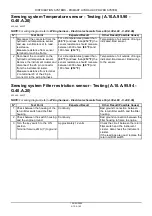
Sensing system Temperature sensor - Testing (A.10.A.95.90 -
G.40.A.20)
435, 445, 445CT
NOTE:
For wiring diagram refer to
Wiring harness - Electrical schematic frame 06 (A.30.A.88 - C.20.E.06)
N°
Test Point
Expected Result
Other Result (Possible Cause)
1 Disconnect the connector from the
hydraulic oil temperature sensor
and use a voltmeter set to read
resistance.
Measure resistance from sensor
terminal to machine frame.
For oil temperatures greater than
(60 °F)
and less than
(212 °F)
the
sensor resistance should measure
between 4300 ohms
(60 °F)
and
180 ohms
(212 °F)
Temperature of oil outside of range
indicated. Bad sensor.
2 Reconnect the connector to the
hydraulic oil temperature sensor.
Remove the instrument cluster and
disconnect the 26 pin connector
from the instrument cluster.
Measure resistance from terminal
2 to terminal 20 of the 26 pin
connector in the wiring harness.
For oil temperatures greater than
(60 °F)
and less than
(212 °F)
the
sensor resistance should measure
between 4300 ohms
(60 °F)
and
180 ohms
(212 °F)
Temperature of oil outside of range
indicated. Bad sensor. Bad wiring
to the sensor.
Sensing system Filter restriction sensor - Testing (A.10.A.95.94 -
G.40.A.20)
435, 445, 445CT
NOTE:
For wiring diagram refer to
Wiring harness - Electrical schematic frame 06 (A.30.A.88 - C.20.E.06)
N°
Test Point
Expected Result
Other Result (Possible Cause)
1 Check between the housing of the
return
fi
lter switch and the
fi
lter
housing.
Continuity
Bad ground connection between
the return
fi
lter switch and the
fi
lter
housing.
2 Check between the switch housing
and the engine ground.
Continuity
Bad ground connection between the
fi
lter housing to frame to engine.
3 Turn the key switch to the ON
position.
Terminal for wire 261A (Y) to ground.
Approximately 12 volts
Check the circuit between the return
fi
lter switch and the instrument
cluster. Also check the instrument
cluster.
If the readings are good, replace the
return oil
fi
lter switch.
1 04/05/2005
A.10.A / 63
Summary of Contents for 435
Page 1: ...REPAIR MANUAL 435 445CT 445 6 75491 1 04 05 2005 ...
Page 3: ...INTRODUCTION 6 75491 1 04 05 2005 1 ...
Page 15: ...INTRODUCTION bs04e020_1 4 6 75491 1 04 05 2005 13 ...
Page 16: ...INTRODUCTION bs04e021_1 5 6 75491 1 04 05 2005 14 ...
Page 19: ...REPAIR MANUAL DISTRIBUTION SYSTEMS 435 445CT 445 39702 1 04 05 2005 A ...
Page 86: ...39703 1 04 05 2005 A 10 A 66 ...
Page 104: ...39704 1 04 05 2005 A 12 A 18 ...
Page 126: ...39705 1 04 05 2005 A 16 A 22 ...
Page 127: ...DISTRIBUTION SYSTEMS A ELECTRICAL POWER SYSTEM 30 A 435 445CT 445 39706 1 04 05 2005 A 30 A 1 ...
Page 237: ...DISTRIBUTION SYSTEMS A LIGHTING SYSTEM 40 A 435 445CT 445 39707 1 04 05 2005 A 40 A 1 ...

