background image

Contents

INTRODUCTION

Engine....................................................................................... 10

[10.001] Engine and crankcase . . . . . . . . . . . . . . . . . . . . . . . . . . . . . . . . . . . . . . . . . . . . . . . . . . . . . . . . . . . . . 10.1

[10.202] Air cleaners and lines . . . . . . . . . . . . . . . . . . . . . . . . . . . . . . . . . . . . . . . . . . . . . . . . . . . . . . . . . . . . . . 10.2

[10.500] Selective Catalytic Reduction (SCR) exhaust treatment . . . . . . . . . . . . . . . . . . . . . . . . . . . 10.3

[10.400] Engine cooling system . . . . . . . . . . . . . . . . . . . . . . . . . . . . . . . . . . . . . . . . . . . . . . . . . . . . . . . . . . . . . 10.4

[10.414] Fan and drive . . . . . . . . . . . . . . . . . . . . . . . . . . . . . . . . . . . . . . . . . . . . . . . . . . . . . . . . . . . . . . . . . . . . . . 10.5

[10.310] Aftercooler. . . . . . . . . . . . . . . . . . . . . . . . . . . . . . . . . . . . . . . . . . . . . . . . . . . . . . . . . . . . . . . . . . . . . . . . . . 10.6

[10.304] Engine lubrication system . . . . . . . . . . . . . . . . . . . . . . . . . . . . . . . . . . . . . . . . . . . . . . . . . . . . . . . . . . 10.7

Transmission.............................................................................. 21

[21.113] Powershift transmission . . . . . . . . . . . . . . . . . . . . . . . . . . . . . . . . . . . . . . . . . . . . . . . . . . . . . . . . . . . . 21.1

[21.135] Powershift transmission external controls. . . . . . . . . . . . . . . . . . . . . . . . . . . . . . . . . . . . . . . . . . 21.2

[21.155] Powershift transmission internal components. . . . . . . . . . . . . . . . . . . . . . . . . . . . . . . . . . . . . . 21.3

[21.700] Torque converter . . . . . . . . . . . . . . . . . . . . . . . . . . . . . . . . . . . . . . . . . . . . . . . . . . . . . . . . . . . . . . . . . . . 21.4

Four-Wheel Drive (4WD) system .................................................. 23

[23.314] Drive shaft. . . . . . . . . . . . . . . . . . . . . . . . . . . . . . . . . . . . . . . . . . . . . . . . . . . . . . . . . . . . . . . . . . . . . . . . . . 23.1

Front axle system ....................................................................... 25

[25.100] Powered front axle . . . . . . . . . . . . . . . . . . . . . . . . . . . . . . . . . . . . . . . . . . . . . . . . . . . . . . . . . . . . . . . . . 25.1

[25.102] Front bevel gear set and differential . . . . . . . . . . . . . . . . . . . . . . . . . . . . . . . . . . . . . . . . . . . . . . . 25.2

[25.108] Final drive hub, steering knuckles, and shafts . . . . . . . . . . . . . . . . . . . . . . . . . . . . . . . . . . . . . 25.3

Rear axle system........................................................................ 27

[27.100] Powered rear axle. . . . . . . . . . . . . . . . . . . . . . . . . . . . . . . . . . . . . . . . . . . . . . . . . . . . . . . . . . . . . . . . . . 27.1

[27.106] Rear bevel gear set and differential . . . . . . . . . . . . . . . . . . . . . . . . . . . . . . . . . . . . . . . . . . . . . . . . 27.2

[27.120] Planetary and final drives . . . . . . . . . . . . . . . . . . . . . . . . . . . . . . . . . . . . . . . . . . . . . . . . . . . . . . . . . . 27.3

Brakes and controls .................................................................... 33

[33.202] Hydraulic service brakes . . . . . . . . . . . . . . . . . . . . . . . . . . . . . . . . . . . . . . . . . . . . . . . . . . . . . . . . . . . 33.1

47881872_EN 24/06/2015

Summary of Contents for 721F Tier4B

Page 1: ...1 2 721F Wheel Loader SERVICE MANUAL Wheel Loader 721F Tier4B Part number 47881872 English June 2015 2015 CNH Industrial Italia S p A All Rights Reserved SERVICE MANUAL Part number 47881872...

Page 2: ...SERVICE MANUAL 721F XR 721F XT 721F ZBAR 47881872_EN 24 06 2015 EN...

Page 3: ...transmission external controls 21 2 21 155 Powershift transmission internal components 21 3 21 700 Torque converter 21 4 Four Wheel Drive 4WD system 23 23 314 Drive shaft 23 1 Front axle system 25 25...

Page 4: ...701 Front loader arm hydraulic system 35 8 35 723 Front loader bucket hydraulic system 35 9 35 734 Tool quick coupler hydraulic system 35 10 Frames and ballasting 39 39 100 Frame 39 1 Steering 41 41 1...

Page 5: ...ore information Please click here Then get the complete manual NOTE If there is no response to click on the link above please download the PDF document first and then click on it Have any questions pl...

Page 6: ...controls 55 11 55 051 Cab Heating Ventilation and Air Conditioning HVAC controls 55 12 55 050 Heating Ventilation and Air Conditioning HVAC control system 55 13 55 047 Steering control system 55 14 55...

Page 7: ...INTRODUCTION 47881872_EN 24 06 2015 1...

Page 8: ...How to use the maintenance standard and precautions 14 Basic instructions Precaution for disassembly and assembly 16 Basic instructions Electrical equipment precautions 18 Consumables 19 Consumables...

Page 9: ...or serious injury CAUTION indicates a hazardous situation that if not avoided could result in minor or moderate injury FAILURE TO FOLLOW DANGER WARNING AND CAUTION MESSAGES COULD RESULT IN DEATH OR S...

Page 10: ...om any other position than the operator s seat TULI12WEX2004AA 1 Never carry out any operation on the machine when the engine is running except when specifically indicated Stop the engine and ensure t...

Page 11: ...tections Goggles with lateral shield or masks for eye protection Do not wear rings wristwatches jewelry unbuttoned or flapping clothing such as ties torn clothes scarves open jackets or shirts with op...

Page 12: ...the cap while engine is hot wear safety clothes and equipment then loosen the cap slowly to relieve the pressure gradually When checking the fuel oil and coolant levels use lights and lamps explicitl...

Page 13: ...tally be pierced when the heat expands beyond the area immediately heated Arrange for temporary fire resistant shields to protect hoses or other components during welding or torch use Have any visible...

Page 14: ...outer sheath will allow water penetra tion Concealed corrosion of the wire reinforcement could subsequently occur along the hose length with resultant hose failure Ballooning of the hose indicates an...

Page 15: ...id vomiting Drink water to rinse your mouth Consult a doctor EYES Rinse abundantly with water for 15 min and con sult a doctor When the electrolyte of a battery is frozen it can ex plode if you attemp...

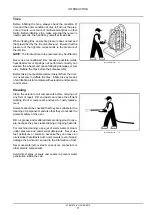
Page 16: ...oil or fuel Fuel or oil spills can cause slipping hazards thoroughly contain and clean affected areas Always tighten the safety plugs of fuel tank and hydraulic oil tank firmly Never use fuel to clean...

Page 17: ...ires Inflate tires by means of an inflation pistol complete with extension and pressure control valve TULI12WEX2020AA 17 Cleaning Clean the exterior of all components before carrying out any form of r...

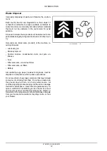
Page 18: ...ion rests and pure an tifreeze Fuel Filter elements oil and fuel filters Filter elements air filters Battery Also polluting rags paper sawdust and gloves must be disposed in compliance with the same p...

Page 19: ...sibility for damages caused by parts and or components not approved by the manu facturer including those used for the servicing or repair of the product manufactured or marketed by the manufacturer In...

Page 20: ...at which reconditioning is impossible without replacement of parts If the value is expected to exceed the service limit before next inspection and correction are performed replace the parts immediate...

Page 21: ...P and recommend that they should be replaced regularly INSPECTION AND REPLACEMENT OF OILS AND GREASES In performing maintenance it is necessary for the user to familiarize himself with how to handle t...

Page 22: ...assembling and assembling hydraulic equipment Before removing lines release the pressure of hydraulic oil tank or open the cover on the return side to tank and take out the filter Drain the oil in rem...

Reviews: