7 - MAINTENANCE
Wheels - Tire inflating
WARNING
Explosion hazard!
Never weld on a wheel. Welding can cause stresses that will cause a wheel to crack or break unexpect-
edly. Tires can separate explosively during welding. Always have a qualified tire mechanic service
wheels and tires.
Failure to comply could result in death or serious injury.
W0124A
Prior operation:
Keep all non-authorized personnel clear of the area. Park the machine on level ground, in neutral with the parking
brake applied. Lower the bucket/attachment to the ground.
Tire service
721G Service specifications - Normal work tire inflations
Tire type
Front pressure
Rear pressure
20.5 R25 Radial and Bias
3.4 bar
(
49.3 psi
)
2.8 bar
(
40.6 psi
)
620/70 R26
4 bar
(
58.0 psi
)
3.0 bar
(
43.5 psi
)
750/55 R26.5
4.5 bar
(
65.2 psi
)
3.5 bar
(
50.8 psi
)
750/65 R26 (MEGAXBIB)
3.4 bar
(
49.3 psi
)
2.1 bar
(
30.5 psi
)
821G Service specifications - Normal Work Tire Inflations
Tire type
Front pressure
Rear pressure
23.5 R25 Radial and Bias
3.4 bar
(
49.3 psi
)
2.8 bar
(
40.6 psi
)
710/65 R26 Radial (CEREXBIB)
2 bar
(
29.0 psi
)
1.6 bar
(
23.2 psi
)
NOTE:
for continuous operation at maximum travel speed, consult tire manufacturer for limitations on total distance
traveled per hour.
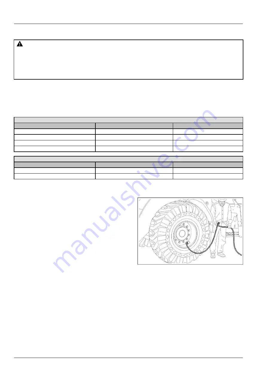
To add air to a tire:
1.
Use an air hose with a remote shut-off valve and a
self-locking air chuck. Put the tire in a restraining
cage if possible.
2.
Stand BEHIND the tread of the tire and make sure
ALL personnel are away from the side of the tire
before you start.
3.
Inflate the tire to the recommended air pressure.
DO NOT inflate the tire more than the recom-
mended pressure.
LEIL16WHL0199AA
1
Tire or rim service
Always have a qualified tire technician service the tires
and rims for this machine. It is recommended that you
have this technician inflate the tires. To prevent acci-
dents, use a restraining device (tire inflation cage), cor-
rect equipment, and correct procedure.
Explosive separation of the tire, or the tire and/or rim
parts can cause serious injury or death.
7-84
Summary of Contents for 721G Stage IV
Page 24: ...1 GENERAL INFORMATION Waste Handler WH configuration LEIL18WHL1118FB 3 721G 1 18 ...
Page 26: ...1 GENERAL INFORMATION LEIL17WHL2018FB 5 821G 1 20 ...
Page 29: ...1 GENERAL INFORMATION LEIL19WHL0584H 1 1 23 ...
Page 30: ...1 GENERAL INFORMATION 1 24 ...
Page 51: ...2 SAFETY INFORMATION Empty tool LEEN11T0024AA 20 2 21 ...
Page 84: ...2 SAFETY INFORMATION 2 54 ...
Page 162: ...3 CONTROLS AND INSTRUMENTS Inducement and validation re starts LEIL14WHL0394HA 2 3 78 ...
Page 163: ...3 CONTROLS AND INSTRUMENTS Validation re start procedure LEIL15WHL0608HA 3 3 79 ...
Page 189: ...4 OPERATING INSTRUCTIONS RCPH10WHL045BAH 7 4 15 ...
Page 191: ...4 OPERATING INSTRUCTIONS RCPH10WHL045BAH 9 4 17 ...
Page 193: ...4 OPERATING INSTRUCTIONS RCPH10WHL045BAH 12 4 19 ...
Page 208: ...4 OPERATING INSTRUCTIONS 4 34 ...
Page 222: ...5 TRANSPORT OPERATIONS 5 14 ...
Page 259: ...7 MAINTENANCE LEIL17WHL1665H 5 721G 7 21 ...
Page 260: ...7 MAINTENANCE LEIL17WHL1665H 6 821G 7 22 ...
Page 267: ...7 MAINTENANCE DEF AdBlue technical faults LEIL14WHL0392HA 4 7 29 ...
Page 291: ...7 MAINTENANCE LEIL18WHL1152AA 14 821G 7 53 ...
Page 300: ...7 MAINTENANCE LEIL15WHL1846AB 2 821G 7 62 ...
Page 313: ...7 MAINTENANCE LEIL18WHL1154FA 1 LEIL18WHL1155FA 2 7 75 ...
Page 360: ...7 MAINTENANCE 9 Re install all the covers guards and steps previously removed 7 122 ...
Page 417: ...7 MAINTENANCE Waste Handler WH models LEIL17WHL2020FA 2 7 179 ...
Page 436: ...8 SPECIFICATIONS 721G Loader Lift Arms Specifications LEIL16WHL0629FB 1 8 10 ...
Page 445: ...8 SPECIFICATIONS LEIL16WHL0629FB 4 8 19 ...
Page 461: ...8 SPECIFICATIONS LEIL16WHL0629FB 10 8 35 ...
Page 470: ...8 SPECIFICATIONS LEIL16WHL0629FB 13 8 44 ...
Page 480: ...8 SPECIFICATIONS 8 54 ...
Page 516: ...9 ACCESSORIES 9 36 ...
Page 520: ...Windows 3 86 Windshield washer fluid level Check 7 163 ...
Page 521: ......

