DISTRIBUTION SYSTEMS - PRIMARY HYDRAULIC POWER SYSTEM
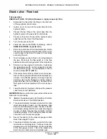
Stack valve - Flow test
Prior operation:
USER PLATFORM - Tilt (E.34.A) Reservoir - Apply vacuum (A.10.A)
1.
Disconnect the hose from the fitting on the inlet port
of the equipment control valve.
2.
Install a tee in the end of the outlet hose from the
hydraulic pump.
3.
Connect the tee fitting at the outlet hose from the
hydraulic pump to the equipment control valve.
4.
Connect a hose from the tee at the hydraulic pump
outlet hose to the inlet of the Flowmeter.
5.
Turn the vacuum pump off.
6.
Lower and secure the ROPS cab/canopy, refer to
USER PLATFORM - Lower (E.34.A).
7.
Place the outlet hose of the Flowmeter back into the
fill port of the reservoir below the level of the oil. Se
cure the hose to the fill port to prevent it from falling
out during the test.
8.
Open the pressure Load Valve on the Flowmeter all
the way. Make sure the flow switch is in the flow
position and move the range switch to the HI position.
9.
Start and run the engine at full throttle. Push down
the temperature switch on the Flowmeter and read
the temperature gauge. The temperature of the oil
must be at least
52 °C (125 °F).
10. If the temperature of the hydraulic oil is not as speci
fied, run the engine at full throttle, hold the blade con
trol lever in the RAISE position and slowly close the
pressure valve on the Flowmeter until the pressure
gauge indicates 103 bar (1500 psi). Continue to run
the engine until the temperature of the oil is as spec
ified.
11. Lower the blade to the ground and open the pressure
Load Valve on the Flowmeter.
IMPORTANT: Make sure that everyone is clear of the dozer
blade prior to proceeding.
12. Maintain the engine speed at full throttle and hold the
blade control lever in the RAISE position.
13. This step will indicate the pressure at which the main
relief valve begins to open. As the pressure Load
Valve on the Flowmeter is closed, the flow indication
will decrease slowly until the main relief valve begins
to open at which time the flow indication will start
decreasing rapidly. STOP closing the pressure Load
Valve and read the pressure gauge.
14. Record the reading of the pressure gauge as Main
Relief Valve begins to open.
15. This step will indicate the pressure at which the main
relief valve is completely open. Continue to close the
pressure valve on the Flowmeter until the indication
of the flow gauge is zero. This is the pressure at
which the main relief valve is completely open.
87728445 1 2/28/2008
A.10.A
I
28
Summary of Contents for 750L
Page 1: ...REPAIR MANUAL 750L 850L 87728445 1 2 28 2008 ...
Page 4: ...87728445 1 2 28 2008 Find manuals at http best manuals com search s CASE 87728445 ...
Page 18: ...INTRODUCTION 87728445 1 2 28 2008 14 ...
Page 19: ...REPAIR MANUAL DISTRIBUTION SYSTEMS 750L 850L 87728445 1 2 28 2008 A ...
Page 51: ...This as a preview PDF file from best manuals com Download full PDF manual at best manuals com ...

