CHAPTER 6 - MAINTENANCE AND ADJUSTMENTS
6-7
6-34551NA
Issued 8-04 Bur
INSTALLATION
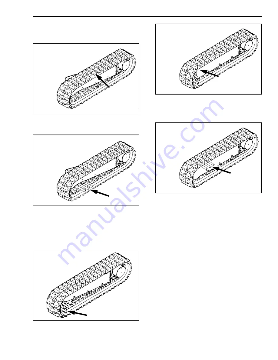
1. Place the track on the sprocket wheel and on the
side-member.
CS98B246
Figure 15
2. Place the tubes in the notches of the track in
front of the idler wheel.
CS98B247
Figure 16
3. Operate the travel lever of the track concerned in
the reverse travel direction. Stop the movement
when the tubes are pressing against the idler
wheel.
4. Stop the engine and remove the starter switch
key.
CS98B248
Figure 17
5. Place the track on the idler wheel.
CS98B209
Figure 18
6. Operate the travel lever of the concerned track to
remove the tubes from the track.
7. Adjust the tension. See Track tension value.
CS98B249
Figure 19
Summary of Contents for CX135SR
Page 6: ...IV Issued 8 04 Bur 6 34551NA CHAPTER 9 INDEX...
Page 12: ...CHAPTER 1 GENERAL INFORMATION 1 6 Issued 8 04 Bur 6 34551NA NOTES...
Page 14: ...CHAPTER 2 SAFETY DECALS AND HAND SIGNALS 2 2 Issued 8 04 Bur 6 34551NA NOTES...
Page 60: ...CHAPTER 3 INSTRUMENTS AND CONTROLS 3 32 Issued 8 04 Bur 6 34551NA...
Page 62: ...CHAPTER 4 OPERATING INSTRUCTIONS 4 2 Issued 8 04 Bur 6 34551NA...
Page 82: ...CHAPTER 4 OPERATING INSTRUCTIONS 4 22 Issued 8 04 Bur 6 34551NA NOTES...
Page 132: ...CHAPTER 5 LUBRICATION FILTERS AND FLUIDS 5 50 Issued 8 04 Bur 6 34551NA NOTES...
Page 134: ...CHAPTER 6 MAINTENANCE AND ADJUSTMENTS 6 2 Issued 8 04 Bur 6 34551NA...
Page 152: ...CHAPTER 6 MAINTENANCE AND ADJUSTMENTS 6 20 Issued 8 04 Bur 6 34551NA NOTES...
Page 154: ...CHAPTER 7 ELECTRICAL 7 2 Issued 8 04 Bur 6 34551NA NOTES...
Page 164: ...CHAPTER 8 SPECIFICATIONS 8 2 Issued 8 04 Bur 6 34551NA...
Page 183: ...CHAPTER 8 SPECIFICATIONS 8 21 6 34551NA Issued 8 04 Bur NOTES...
Page 184: ...CHAPTER 8 SPECIFICATIONS 8 22 Issued 8 04 Bur 6 34551NA...


