1 - GENERAL INFORMATION
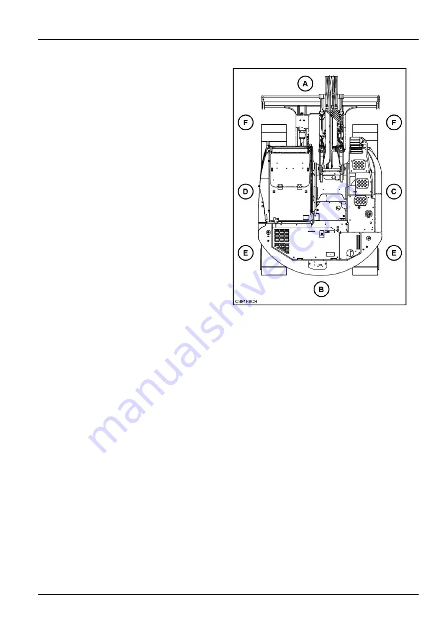
Left, right, front and rear of the machine
The terms "Right-hand", "Left-hand", "Front" and "Rear"
are used in this manual to indicate the sides as they are
seen from the operator's seat when the cab is over the
idler wheels.
ATTENTION:
The illustration opposite shows the machine
in normal travel position. In normal travel position, the cab
is over the idler wheels. The travel reduction gears are at
the rear of the upperstructure.
(A)
Front
(B)
Rear
(C)
Right-hand side
(D)
Left-hand side
(E)
Travel motors
(F)
Idler wheels
C891F8C9
1
Electro-magnetic interference (EMC)
Interference may arise as a result of add
‐
on equipment which may not necessarily meet the required standards. As
such interference can result in serious malfunction of the unit and/or create unsafe situations, you must observe the
following:
• The maximum power of emission equipment (radio, telephones, etc.) must not exceed the limits imposed by the
national authorities of the country where you use the machine.
• The electro
‐
magnetic field generated by the add
‐
on system should not exceed
24 V/m
at any time and at any
location in the proximity of electronic components.
• The add
‐
on equipment must not interfere with the functioning of the on board electronics.
Failure to comply with these rules will render the CASE CONSTRUCTION warranty null and void.
1-9
Summary of Contents for CX145C SR
Page 6: ......
Page 18: ...1 GENERAL INFORMATION 1 12 ...
Page 29: ...2 SAFETY INFORMATION E5054225_TU 4 2 11 ...
Page 132: ...3 CONTROLS INSTRUMENTS 3 82 ...
Page 160: ...4 OPERATING INSTRUCTIONS 4 Operate the arm control to unhook the tool KKZVLU 024A 14 4 28 ...
Page 180: ...4 OPERATING INSTRUCTIONS 4 48 ...
Page 206: ...6 MAINTENANCE Offset boom pin 10 07C803C9 17 6 16 ...
Page 207: ...6 MAINTENANCE Arm backhoe bucket 375EFD72 18 AB1F527A 19 6 17 ...
Page 298: ...8 SPECIFICATIONS Offset maximum left EACB5F36 6 See next page for the value 8 14 ...
Page 300: ...8 SPECIFICATIONS 8 16 ...


