4 - OPERATING INSTRUCTIONS
Optional hand control levers configuration
The switches can be wired by your CASE CONSTRUCTION Dealer to control either single function or dual function
hydraulic configurations.
The machine can have two types of auxiliary hydraulic circuits. One circuit can be used for single flow equipment, such
as hydraulic breakers. The second type of circuit is intended for use with single flow or double flow (with continuous
flow) for use with demolition concrete crushers, etc.
The optional control buttons can be used to activate and control the system for multipurpose tools such as a crusher,
nibbler, etc. Additionally they can be configured to regulate the preset hydraulic oil flow for the specific tool when
pressed.
See your CASE CONSTRUCTION Dealer for specific options and controls for hydraulic hammers, breakers, nibblers,
or other special attachments.
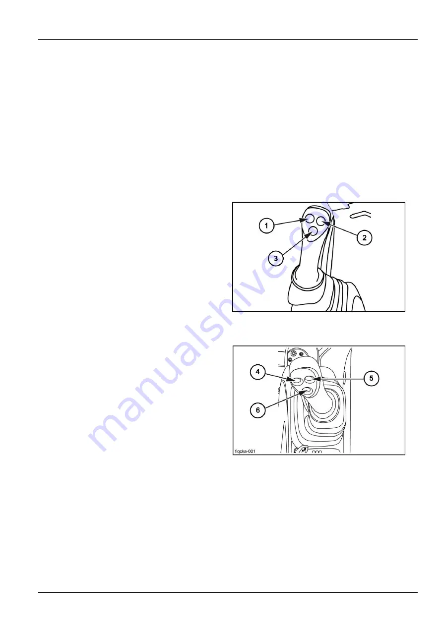
Left-hand control lever
The left hand control lever can control four machine oper-
ations for the operator’s convenience.
The radio mute switch is located on the underneath side
of the left hand control lever, while button
(3)
enables the
horn.
Two additional function switches
(1)
and
(2)
are available
for optional use.
NZIMV6-002B
1
Right-hand control lever
The right hand control lever controls the engine idle speed
selector
(6)
. This button enables automatic engine idle
without operating the throttle button.
To select idle speed, press and release the control for the
engine automatically to go into idle speed.
The message “Engine idling” will appear on the display
panel.
When the control is pressed and released once more the
engine will revert to its original speed and the message
on the display panel will disappear.
The two additional buttons
(4)
and
(5)
on the right hand
control lever are for optional tools such as a hydraulic
hammer, breakers, or other special attachments.
FIQCKA-001C
2
4-45
Summary of Contents for CX145C SR
Page 6: ......
Page 18: ...1 GENERAL INFORMATION 1 12 ...
Page 29: ...2 SAFETY INFORMATION E5054225_TU 4 2 11 ...
Page 132: ...3 CONTROLS INSTRUMENTS 3 82 ...
Page 160: ...4 OPERATING INSTRUCTIONS 4 Operate the arm control to unhook the tool KKZVLU 024A 14 4 28 ...
Page 180: ...4 OPERATING INSTRUCTIONS 4 48 ...
Page 206: ...6 MAINTENANCE Offset boom pin 10 07C803C9 17 6 16 ...
Page 207: ...6 MAINTENANCE Arm backhoe bucket 375EFD72 18 AB1F527A 19 6 17 ...
Page 298: ...8 SPECIFICATIONS Offset maximum left EACB5F36 6 See next page for the value 8 14 ...
Page 300: ...8 SPECIFICATIONS 8 16 ...


