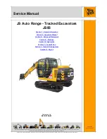
3 - CONTROLS/INSTRUMENTS
1.
Engine coolant temperature gauge
Displays the temperature of the engine coolant.
The lower zone indicates that the engine coolant tem-
perature is low.
When the temperature gauge display reaches the up-
per zone, an alarm sounds and "Over heat" is dis-
played (see "Message screens").
Lower the engine speed.
If the temperature does not go down, stop the engine,
remove the ignition key, and investigate the cause.
2.
Hydraulic oil temperature gauge
Displays the temperature of the hydraulic oil.
The lower zone indicates that the hydraulic oil tem-
perature is low.
When the temperature gauge display reaches the up-
per zone, an alarm sounds and "Over heat" is dis-
played (see "Message screens").
Lower the engine speed.
If the temperature does not go down, stop the engine,
remove the ignition key, and investigate the cause.
3.
Fuel gauge
Displays the remaining amount of fuel by the number
of lit segments.
When all are lit, it indicates that the fuel tank is full.
When only 1 is lit, an alarm sounds and "Low fuel" is
displayed (see "Message screens").
NOTE:
It is not necessary to wait until the fuel tank
is empty before filling with fuel. If the tank becomes
empty, air bleeding of the fuel system is required.
4.
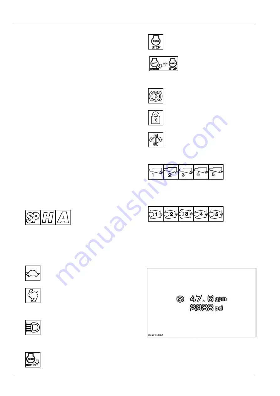
Work mode icon
These indicators display the initial work mode and
the engine speed that was selected with the engine
acceleration button and work mode selector. (Refer
to page
3-58
).
5.
Travel mode icon
At low speed, is displayed.
At high speed, is displayed.
6.
Working light
Displayed when the light is on.
7.
Engine auto idling and stop selection display
Displayed when auto idling is selected.
“Auto n/min”.
Displayed when auto stop is selected.
“Auto idle stop”.
Displayed when auto idling and
auto stop are selected.
“Auto
n/min” and “Auto idle stop”.
8.
Free swing, swing parking and anti-theft protection
Displayed when swing parking is operat-
ing (for service use only).
Displayed when the anti-theft protection
function is operating.
Displayed when free swing is operating.
9.
Displays the selected attachment
Hydraulic breaker
Crusher grapple
10. Clock display
(Refer to page
3-48
).
11. Auxiliary setting display
When an option circuit is mounted, the selected flow
and pressure are displayed.
MUC8LU-043Z
3
Icon display
The setting that the wiper, idling and glow switches
are switched to are displayed largely in the middle of
display.
• Wiper operation
3-20
Summary of Contents for CX145C SR
Page 6: ......
Page 18: ...1 GENERAL INFORMATION 1 12 ...
Page 29: ...2 SAFETY INFORMATION E5054225_TU 4 2 11 ...
Page 132: ...3 CONTROLS INSTRUMENTS 3 82 ...
Page 160: ...4 OPERATING INSTRUCTIONS 4 Operate the arm control to unhook the tool KKZVLU 024A 14 4 28 ...
Page 180: ...4 OPERATING INSTRUCTIONS 4 48 ...
Page 206: ...6 MAINTENANCE Offset boom pin 10 07C803C9 17 6 16 ...
Page 207: ...6 MAINTENANCE Arm backhoe bucket 375EFD72 18 AB1F527A 19 6 17 ...
Page 298: ...8 SPECIFICATIONS Offset maximum left EACB5F36 6 See next page for the value 8 14 ...
Page 300: ...8 SPECIFICATIONS 8 16 ...


