background image

IOM-764P / PD

2

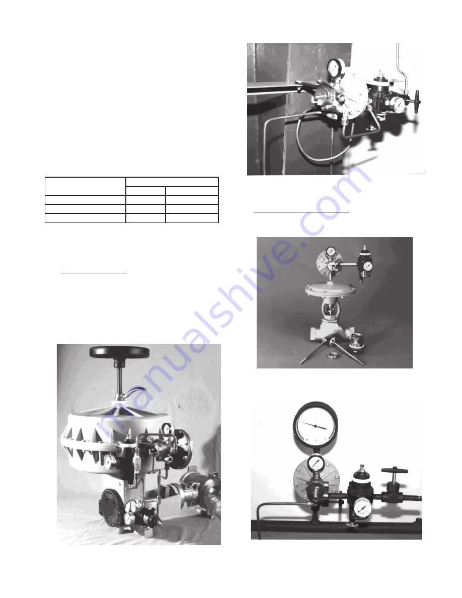
Figure 3

With Option -23; Field Bracket Mounting to Structure

Field Pipe Nipple Mounted

.  Recommend pipe tap 

on top or side of pipe.

Figure 4

Output Pipe Nipple Mounted to Model 2266 Control Valve

Figure 5

Field Pipe Nipple Mounted to Piping

6.  It is recommended as a good practice to locate 

the controller as close as practical to the pressure 
tapping and at a similar elevation. For installations 
where the controller was factory mounted on a 
control valve unit, the pressure tapping should 
be within 6 - 10 feet (2 - 3 meters) of the control 
valve. (Remember to compensate for tappings 
located above the elevation of the controller for 
any liquid pressure head that may occur.)

7.  The controller’s pneumatic output signal (SIG) 

piping or tubing should be limited in length, and 
con sid er ation must be given for the ultimate 
pur pose of the SIG at its final destination. The 
fol low ing are recommended practices:


8.  764P controllers may be mounted by various 

meth ods:


Bracket Mounted

.  Includes a bracket with 

ma chine screws to allow attachment to a fixed 
struc tur al ap pend age; requires specifying Option 
-23. (This is the method utilized when the 764P/
PD is spec i fied to be mounted to a control valve 
ac tu a tor.)

Figure 2

Factory Bracket Mounted to Ranger QCT Control Valve

Purpose

Tubing

Size

Max Length*

SIG to Positioner

1/4" O.D.

100 ft.

SIG to Supply Booster 1/4" O.D. 

100 ft.

LOAD to Actuator

1/4" O.D.

10 - 12 ft.

* Contact factory for longer lengths.

Summary of Contents for 764P

Page 1: ...ositioner I DESCRIPTION AND SCOPE The Model 764P is a pressure controller used for sensing static pressure and outputting a pneumatic signal proportional to the deviation from the setpoint The Model 764PD is a differential pressure controller used for sensing two static pressures HIGH and LOW and outputting a pneumatic signal proportional to the deviation from the setpoint With proper materials se...

Page 2: ...tion of the controller for any liquid pressure head that may occur 7 The controller s pneumatic output signal SIG piping or tubing should be limited in length and consideration must be given for the ultimate purpose of the SIG at its final destination The following are recommended practices 8 764P controllers may be mounted by various methods Bracket Mounted Includes a bracket with machine screws ...

Page 3: ...ate use of the highest quality air supply available If air can not be practically dried and bears oil coalescing filters should be utilized to remove as much oil and water as possible as well as Panel Mounted Not factory provided Requires field provision of a panel opening and support bracket per the below dimensions Common applications Uncommon applications Adjusting Screw Panel 10 32 flat head m...

Page 4: ... flow through the sensor is reduced which increases the output signal Theproportionalbandrestrictionregulates the flow rate of supply air into PORT A PORT B is the exhaust port A 764PD operates the same 4 On reverse acting 764P controllers see Figure 8 the supply enters PORT B not PORT A With an increase in the controlled pressure the supply air flowing through the sensor decreases which reduces t...

Page 5: ...est stability is obtained or up to the maximum of 1 1 2 revolutions 3 Units are factory calibrated to approximately mid range i e 50 150 psig 3 4 10 3 Barg range will havesetpointatapproximately100psig 6 9Barg It is recommended that the unit be field calibrated following installation and prior to startup See SectionVI CALIBRATIONfordetailedprocedure Direct Action Adjust setpoint by rotating adjust...

Page 6: ...ragm cover thin SST material 17 is placed on side s exposed to the process fluid s 764PD requires both sides to be covered if supplied with diaphragm covers 17 6 Replace with new upper case diaphragm O ring 16 upper case 13 and cap screws with nuts 19 and 18 7 Recalibrate per Section VI C Pneumatic Circuit Overhaul 1 Remove output pressure gauge 11 and test calibration If gauge is off 2 psi 0 14 B...

Page 7: ...e sensor O rings 5 The final position should have the sensor pin 2 4 directly above the center of the adjusting screw 2 3 Install the four end plate screws 8 See Figure 11 The rounded end of the sensor plate 15 will touch the diaphragm 16 for the 764P or the pusher post 24 of the 764PD NOTE The previous description is for 764PD s and 764P s in pressure ranges 2 30 Hg 1 30 psig 20 100 psig 50 150 p...

Page 8: ... Install a 1 4 pipe plug in the OUTPUT port of unit 2 Provide an 18 psig 1 2 Barg IAS to the proper port as determined by Table 1 Section II 3 Leave PB as set in Section V C 13 If this setting is unknown rotate the PB needle valve 3 CW until seated Rotate needle valve 3 CCW until indented matchmarks align this is approximately 8 1 4 of a revolution 4 1 Provide a known pressure compressed nitrogen ...

Page 9: ...nt output tubing line length against those indicated herein in Section 11 7 Relocate controller or consider adding an air booster or positioner at the control valve A3 Check for mashed or pinched tubing A4 Installation debris Air blow line A5 Ice in lines Use dry air supply B Insufficient air supply B Increase supply up to 18 20 psig C Too much PB C Decrease PB in 1 8 rev increments Reset setpoint...

Page 10: ...lectminimum parts required for inspection and rebuild Soft Goods Kit Those in column B include minimum trim replacement parts needed plus those Soft Goods parts from column A If the BOM is not available refer to the cross sectional drawings included in this manual for part identification and selection ALocalSalesRepresentativewillprovidequotation for appropriate Kit Number Price and Availability C...

Page 11: ...sembly 450 2500 psig Range ITEM NO DESCRIPTION 12 Diaphragm 13 Upper Case 14 Lower Case 15 Sensor Plate Sub Assembly 15 1 Sensor Plate 15 2 Adaptor 15 3 Retaining Ring 15 4 Spring 16 O ring Diaphragm 17 Diaphragm Cover if supplied 18 Nut 19 Screw 20 Vent Plug Not Sold as individual parts Purchase Sensor Sub_Assembly 2 Figure 12 Model 764P Available Ranges psig Barg 1 30 0 7 2 1 20 100 1 4 6 9 50 1...

Page 12: ...as individual parts Purchase Sensor Sub Assembly 2 ITEM NO DESCRIPTION 1 Housing 2 Sensor Sub Assembly 2 1 Sensor 2 2 End Plate 2 3 Adjusting Screw 2 4 Sensor Pin 2 5 Retainer Clip 3 Needle Valve 5 O Ring Sensor 6 O Ring Sensor Plate 7 O Ring Needle Valve 8 End Plate Screw 9 Name Plate Screw 10 Name Plate Figure 13 Model 764PD 1 4 NPT Tap Available Ranges 1 30 psid 07 2 1 Bard 20 100 psid 1 4 6 9 ...

Page 13: ...g of the process gas depends on the process gas and the inlet and outlet pressures The system designer is responsible for determining whether the process gas temperature may raise under any operating conditions 2 Where the process medium is a liquid or semi solid material with a surface resistance in excess of 1GΩ special precautions shall be taken to ensure the process does not generate electrost...

Page 14: ...RYO D OPT 37 D OPT 20 D OPT 45 DL DL LCC DL OPT 45 BR BR CRYO HP HP LCC HP OPT 45 HP OPT46G HP 1 6 S OPT 40 HP 1 6 S P1 P2 P3 P4 P5 P7 B2 B7 POSR 1 POSR 2 5200P 5300P 135 NW PL NW SO CG PILOT FG1 CONTROL VALVES RANGER 987 PREMIER 964 521 988 988 MB 989 2296 2296HF SCV 30 SCV S FL800 FL200 TANK BLANKETING 8700 8910 8920 8930 8940 2100 2199 3100 3200 3300 3400 3500 3600 3700 1078 1088 1100 1049 5100...

Reviews: