Model FL-200
Inline Thermal Check Valve
INSTRUCTION NO. IOM-FL200
REFERENCE DATA:
FL-200 Series Assembly Drawing No. A88-60200-00.
INSTALLATION:
1. Clean the piping of all foreign material including chips, welding scale, oil, grease and dirt before installing the thermal
trip valve.
2. In placing thread sealant on pipe ends prior to engagement, ensure that excess material is removed and not allowed
to enter the thermal trip valve upon startup.
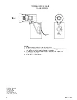
3. Flow Direction: Install so the flow direction matches the flow arrow on the body of the thermal trip valve.
PRINCIPLE OF OPERATION:
1. When the valve is installed it is open.
2. This valve will stay open until it is actuated by the fusible link.
3. This will cause the valve to close.
MAINTENANCE:
1. All valves are leak tested at the factory at 200 PSIG and should be externally leak tight after installation. If after pro-
longed ser vice the valve should leak externally, it is recommended that the valve be replaced or sent to the factory
for rebuilding.
IOM-FL 200
12-04
MAINTENANCE & ASSEMBLY INSTRUCTIONS


